Push-tumble three dimensional navigation system

Inactive Publication Date: 2006-05-09
AUTODESK INC
View PDF8 Cites 19 Cited by
  • Summary
  • Abstract
  • Description
  • Claims
  • Application Information

AI Technical Summary

Benefits of technology

[0007]It is an aspect of the present invention to provide a system for manipulating parameters of a virtual camera with a simple input dev

Problems solved by technology

Because of the high number of different manipulation actions, and because of the number of viewing parameters affected by those manipulations, it has been difficult to effectively and smoothly manipula

Method used


Image

  • Push-tumble three dimensional navigation system
  • Push-tumble three dimensional navigation system
  • Push-tumble three dimensional navigation system

Examples


Example

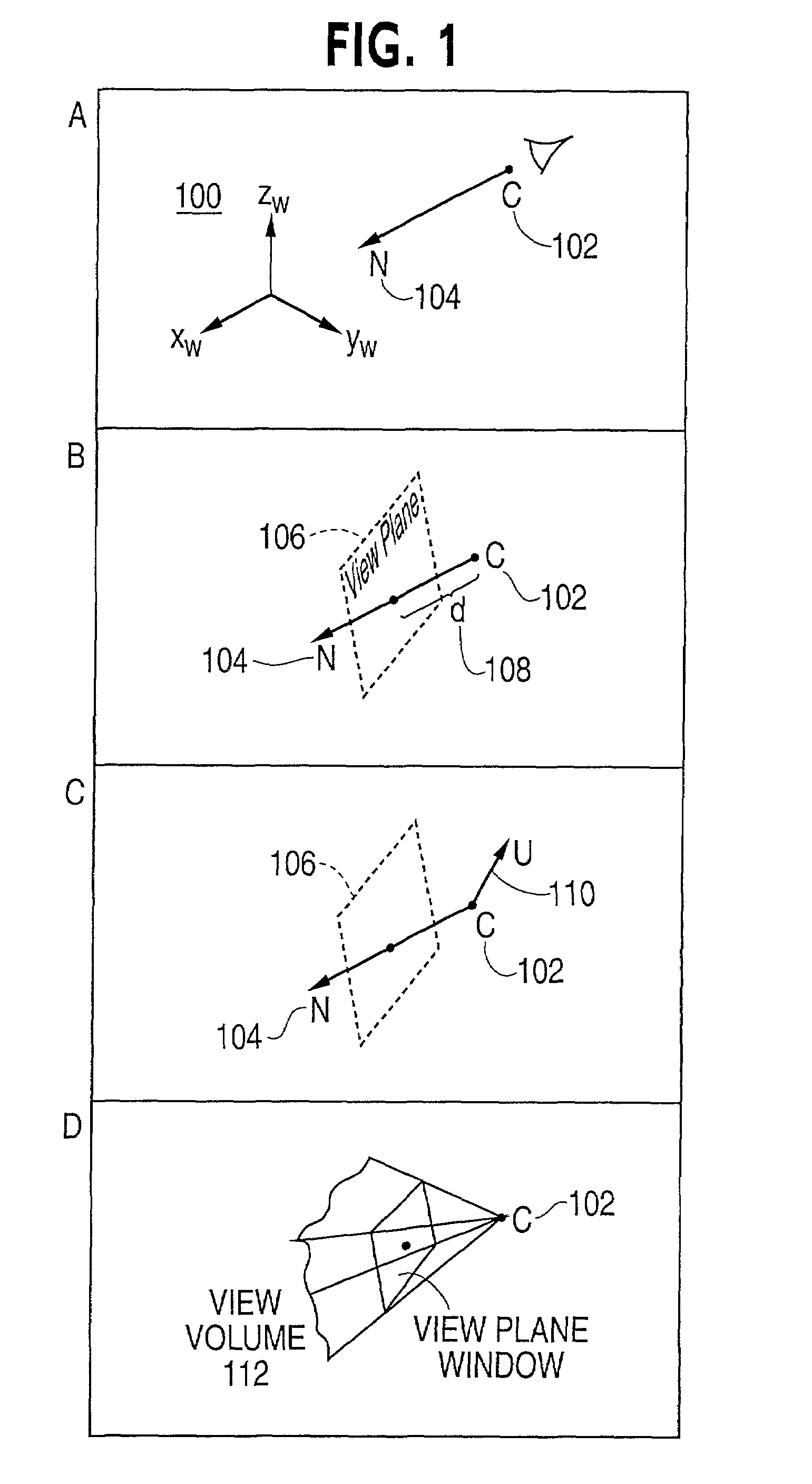
[0040]The present invention is directed to a three-dimensional viewing system. Viewing systems, virtual views, or virtual cameras simulate what a person would see if they were placed within a virtual or three-dimensional space. A viewing system, a view, virtual eye, or virtual camera in part consists of viewing parameters, such as a view point and a viewing direction. A view point establishes the viewer's position within the space being viewed. The view point can be an origin of a coordinate system of the view, or the center of projection together with a view direction. A view direction is usually a vector defining the direction the view is pointed, and is sometimes referred to as the center of view.

[0041]FIG. 1 shows principles that are used to describe a virtual view or virtual eye. In area A, a coordinate system 100 is viewed from view point C 102 at viewing direction N 104. In area B, a view plane 106 is normal to the viewing direction N 104, and is positioned distance d 108 fro...


PUM


Abstract

The present invention relates to a system of interactive navigation of a tool relative to three-dimensional volumetric data. The tool may be a camera or a brush and the volume data may be points, curves, iso-surfaces, geometric surfaces or combinations thereof. Moreover, the volume data may be explicitly or implicitly created. In the case of a camera and a surface, a surface of the model is viewed from an initial view point with an initial view direction. A two-dimensional vector, as by moving a mouse, is used to translate the initial view point to a next view point in a plane normal to the view direction and intersecting the initial view point. A point of the surface that is closest to the next view point may then be found, and the next direction of the view is set to the direction from the next position of the view point to the closest surface point. The closest point is found by casting rays from the next view point. The next view direction may be set to the direction of the ray corresponding to the point with the smallest distance. The next view point may be further translated toward or away from the closest surface point, along the newly set next view direction, to a location that is a same distance from the surface as the initial view point.

Description

BACKGROUND OF THE INVENTION[0001]1. Field of the Invention[0002]The present invention is directed to a system for orbital and volumetric navigation that can be used for three-dimensional tasks such as painting and viewing. More particularly, the present invention allows a user to change a viewpoint of an object by essentially pushing and tumbling the object.[0003]2. Description of the Related Art[0004]Three dimensional viewing systems usually include provisions for manipulating a view. Manipulation is generally designed to affect 6 degrees of freedom of a view; 3 for the view direction, and 3 for the view point or position. In the past, two approaches have been used for manipulating a view. First, separate panning, zooming, and tumbling or rotating operations have been assigned to different input controls or modes. Because of the high number of different manipulation actions, and because of the number of viewing parameters affected by those manipulations, it has been difficult to ef...

Claims


Application Information

Patent Timeline
IPC IPC(8): G06T17/00G06F3/033G06F3/048G06T3/00
CPCG06F3/04815G06T15/20G06T19/00
Inventor KHAN, AZAM
Owner AUTODESK INC
Why Eureka
Try Eureka