Cooling arrangement for an integrated circuit

a cooling arrangement and integrated circuit technology, applied in the direction of electrical equipment, lighting and heating apparatus, electrical equipment contruction details, etc., can solve the problems of ineffective cooling, risk of short circuit of signal paths that are close to the socket or the socket in which the socket is mounted, and more power must be supplied, so as to prevent the formation of condensate and strong cooling of the integrated circuit or processor

Inactive Publication Date: 2006-05-09
EXTREME COOLING TECH
View PDF17 Cites 19 Cited by
  • Summary
  • Abstract
  • Description
  • Claims
  • Application Information

AI Technical Summary

Benefits of technology

[0013]For further prevention of formation of condensate, and with very strong cooling of an integrated circuit or processor, it is an advantage if a bottom flange having a bottom is fixed below the printed circuit board in the area where the wires to the integrated circuit are provided, and that a sealing material is also provided between the bottom flange and the printed circuit.
[0014]Hereby, also wires on the printed circuit board where the socket of a processor is arranged, are effectively protected against formation of condensate.
[0015]It is noted in this connection that when the sealing material has a glass temperature which is below −50°C., it is ensured that the sealing material remains in a plastic state.
[0016]Additionally, when the sealing material is an elastomer, such as ethylene-propylene-diene copolymer, also called butyl rubber, a very effective sealing material is achieved in connection with the sealing of processors which are to be shielded from the ambient air.
[0017]To ensure well-defined cooling of an integrated circuit, it is an advantage if the supply pipe for supplying coolant to the inlet stub in the evaporate is constructed such that the coolant changes its direction, e.g., 90°, when entering the inlet stub, and that the diameter of the inlet stub and of the outlet stub is larger than the diameter of the supply pipe.
[0018]This results in a “steady” flow and a well-defined mixture of coolant in liquid and vapour form in the evaporator, where the vapours will be above the liquid.

Problems solved by technology

However, the situation is that the faster the ICs are to operate, the more power must be supplied to them.
The use of the compressor-based IC cooling systems that are known today involves problems of condensate around the IC which is cooled.
Thus, it is known from U.S. Pat. No. 6,054,676 that the cooling of an integrated circuit, as stated in the patent, has created problems of condensate around the integrated circuit with the consequent risk of short-circuiting of the signal paths that are close to it or the socket in which it is mounted.
One reason is that in practice the heating element heating the surroundings of the IC will also increase the temperature of the IC, which means in turn that the cooling is not as efficient as it could be if the heating could be omitted.

Method used


Image

  • Cooling arrangement for an integrated circuit
  • Cooling arrangement for an integrated circuit
  • Cooling arrangement for an integrated circuit

Examples


Embodiment Construction

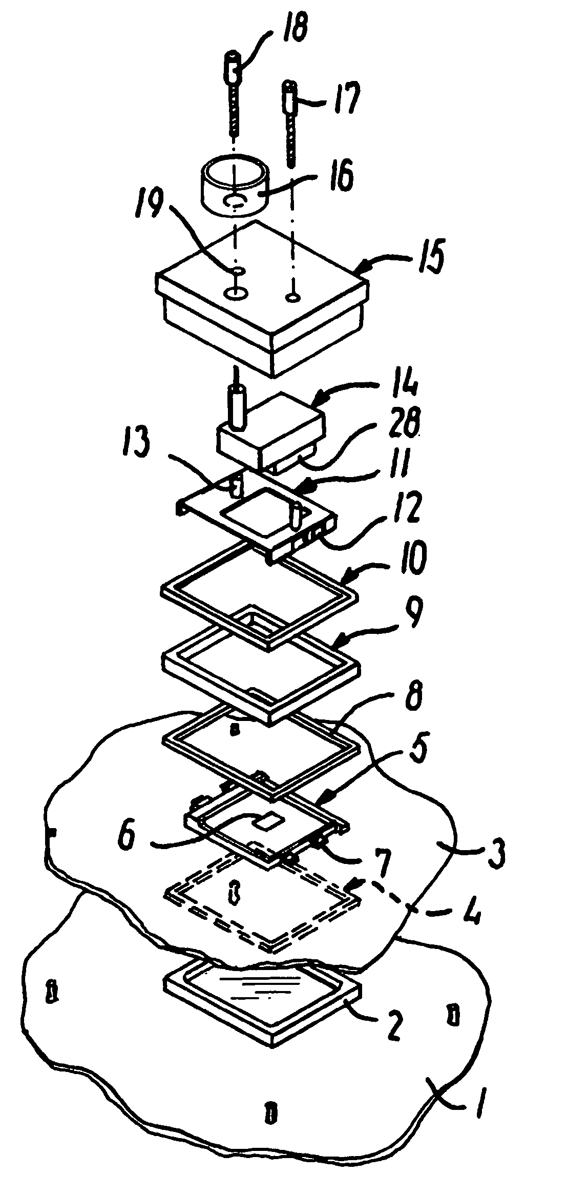
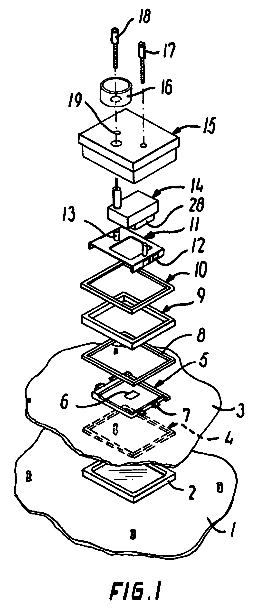
[0028]In FIG. 1, the numeral 1 designates a cabinet portion which forms part of a rack or the like.

[0029]The cabinet has mounted therein a printed circuit board 3 on which inter alia a socket 5 is mounted, the socket centrally carrying an integrated circuit 6. Locking hooks 7, whose function will be described later, are arranged along two of the edges of the socket 5.

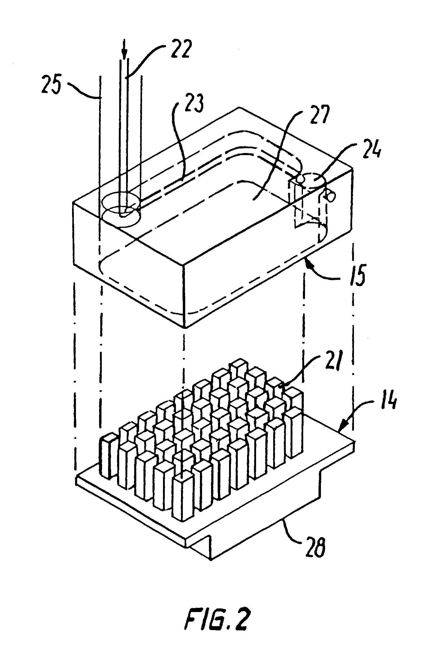
[0030]15 designates a housing on which a lid 14 may be applied, which, as will be explained later, constitutes an evaporator in a cooling arrangement according to the invention. As will also be seen, the housing 15 is formed with through holes, one of which is designated 19, through which screws 17, 18 may be received. Finally, a flange 16 is arranged on the upper side of the housing 15, adapted to receive pipes for the supply of coolant, as will be explained in connection with FIG. 2.

[0031]These screws 17, 18 may be screwed into holes, one of which is designated 13, in a locking part 11 having recesses 12 along two of ...


PUM


Abstract

A cooling arrangement for one or more integrated circuits which are mounted in a socket on a printed circuit board and which each are cooled by a cooling element based on a compressor. The surface of each integrated circuit has arranged thereon a cooling element which is formed by an evaporator in the form of a housing (15) which has a lid with protruding cooling rods. Coolant is supplied to the housing (15) via a supply pipe (22, 23) that ends in an inlet stub (24) in the housing, which is constructed such that the coolant changes its direction, such as 90°, when entering the interior of the housing. The coolant is returned form the housing via an outlet stub (25) which is concentric with the inlet stub (22). The supply pipe has a smaller diameter than the inlet stub (24) and the outlet stub (25), which means that cooling of the coolant and thereby of the cooling rods takes place in the housing, said cooling being transferred to the individual ICs. With a view to avoiding formation of condensate in connection with the cooling process, the housing is fixed against the printed circuit board according to the invention, a sealing material, such as butyl, being arranged between the housing (15) and the printed circuit board (3). For additional sealing, a rear flange may be fixed on the rear side of the printed circuit board in the area where wires are run to the IC, said rear flange being sealed with butyl against the printed circuit board.

Description

BACKGROUND OF THE INVENTION[0001]The invention relates to a cooling arrangement for an integrated circuit which is mounted in a socket on a printed circuit board, wherein a cooling element is arranged on the integrated circuit, and wherein the cooling arrangement and the integrated circuit are thermally insulated from the surroundings in a housing whose edge is fixed against the printed circuit board.THE PRIOR ART[0002]In recent years, cooling of integrated circuits, so-called ICs , has found ever greater use because of the development within the semiconductor technology. An example of this development is the PC systems where the processors, which are the central elements of the computers, constantly enhance their performance. For example, their calculation rates are increased almost month by month.[0003]However, the situation is that the faster the ICs are to operate, the more power must be supplied to them. Conversely, this means that more heat is to be discharged since the perfor...

Claims


Application Information

Patent Timeline
Patent Type & Authority Patents(United States)
IPC IPC(8): H05K7/20H01L23/10H01L23/473
CPCH01L23/10H01L23/473H01L2924/0002H01L2924/00
Inventor ESPERSEN, MORTENKRISTENSEN, THORBEN
Owner EXTREME COOLING TECH
Why Eureka
Try Eureka