Optical multi-level recording medium and optical multi-level recording method

a multi-level recording and optical technology, applied in the field of optical multi-level recording medium and optical multi-level recording method, can solve the problems of poor reading signal quality, difficult to achieve five-stage or more multi-level recording by changing the laser power, etc., and achieve the effect of high read accuracy

Inactive Publication Date: 2006-05-09
TDK CORPARATION
View PDF4 Cites 4 Cited by
  • Summary
  • Abstract
  • Description
  • Claims
  • Application Information

AI Technical Summary

Benefits of technology

[0013]The present invention has been made in order to further study the above technology. Accordingly, an object of the present invention is to provide an optical recording medium, which can achieve multi-stage (multi-level) and high read-accuracy multi-level recording by setting a power of laser beam to a predetermined range.

Problems solved by technology

In the above multi-level recording, a laser beam is irradiated at multiple-stage power in recording; for this reason, in particular, when the power of laser beam gradually becomes large, a problem has arisen such that a signal quality is worsened in reading.
In fact, it is very difficult to achieve five-stage or more multi-level recording by the method of changing a laser power.

Method used


Image

  • Optical multi-level recording medium and optical multi-level recording method
  • Optical multi-level recording medium and optical multi-level recording method
  • Optical multi-level recording medium and optical multi-level recording method

Examples


first embodiment

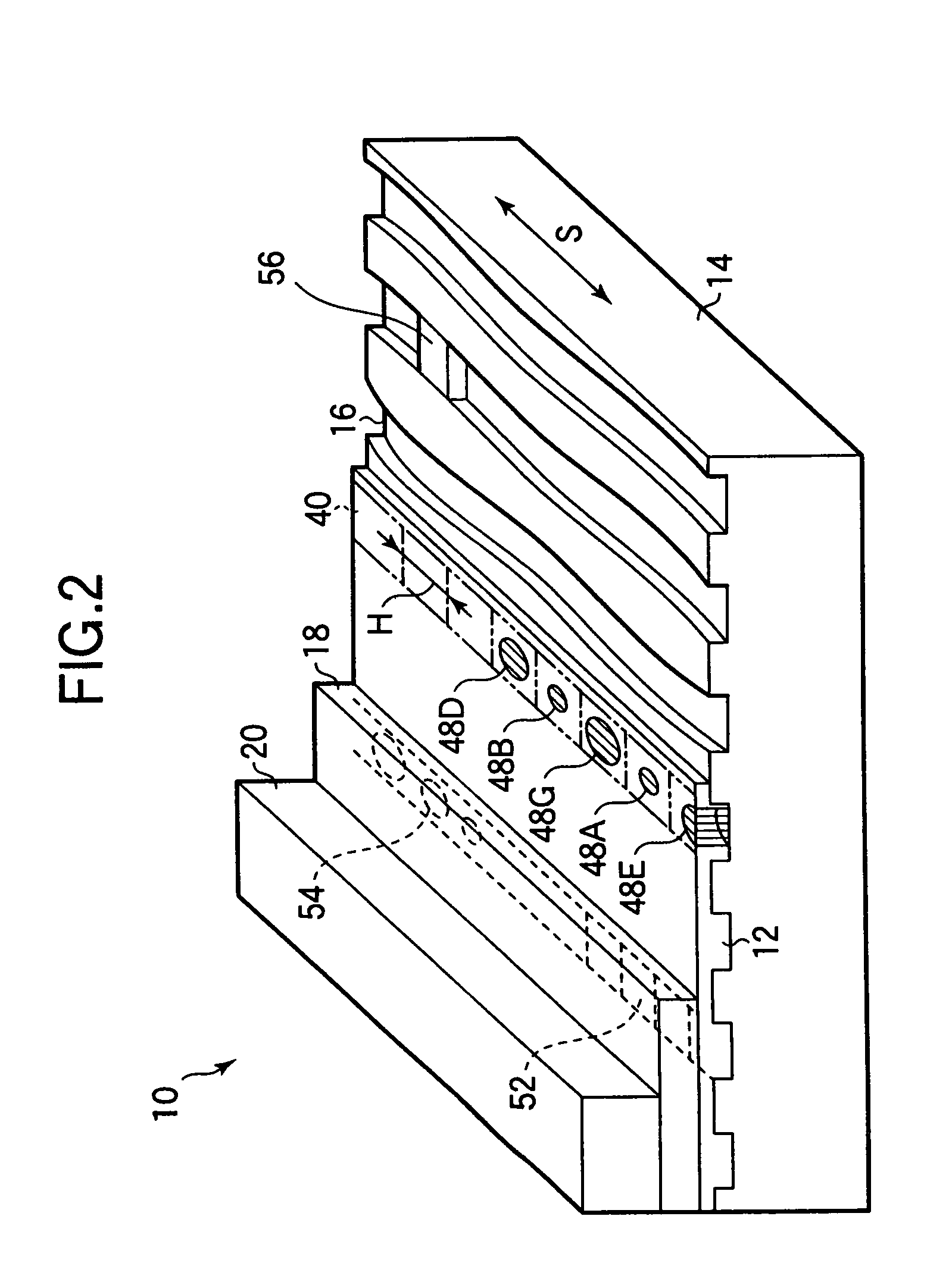
[0073]In FIG. 2, there is shown an optical recording medium (disk) 10 to which the optical recording method according to the present invention is applied. The optical recording medium 10 is a CD-R having a recording layer 12 using a dye, and is composed of a substrate 14 made of transparent base material, the above recording layer 12, a gold or silver reflection film (layer) 18, and a protective layer 20. More specifically, the recording layer 12 is formed out of dye applied so as to cover a laser beam guide groove 16 formed on one side (upper surface in FIG. 2) of the substrate 14. The reflection film 18 is formed on the upper side of the recording layer 12 by spattering or the like, and the protective layer 20 is formed so as to cover the reflection layer 18.

[0074]The dye used for the recording layer 12 is an organic dye including cyanine, mero-cyanine, methine-based dye and its derivative, benzenethiol metal complex, phthalocyanine dye, naphthalocyanine dye, azo dye, etc.
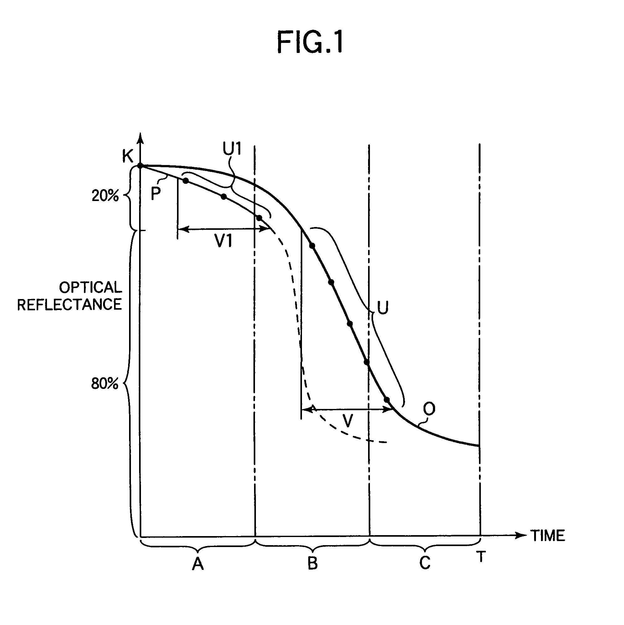
[0075]Th...

third embodiment

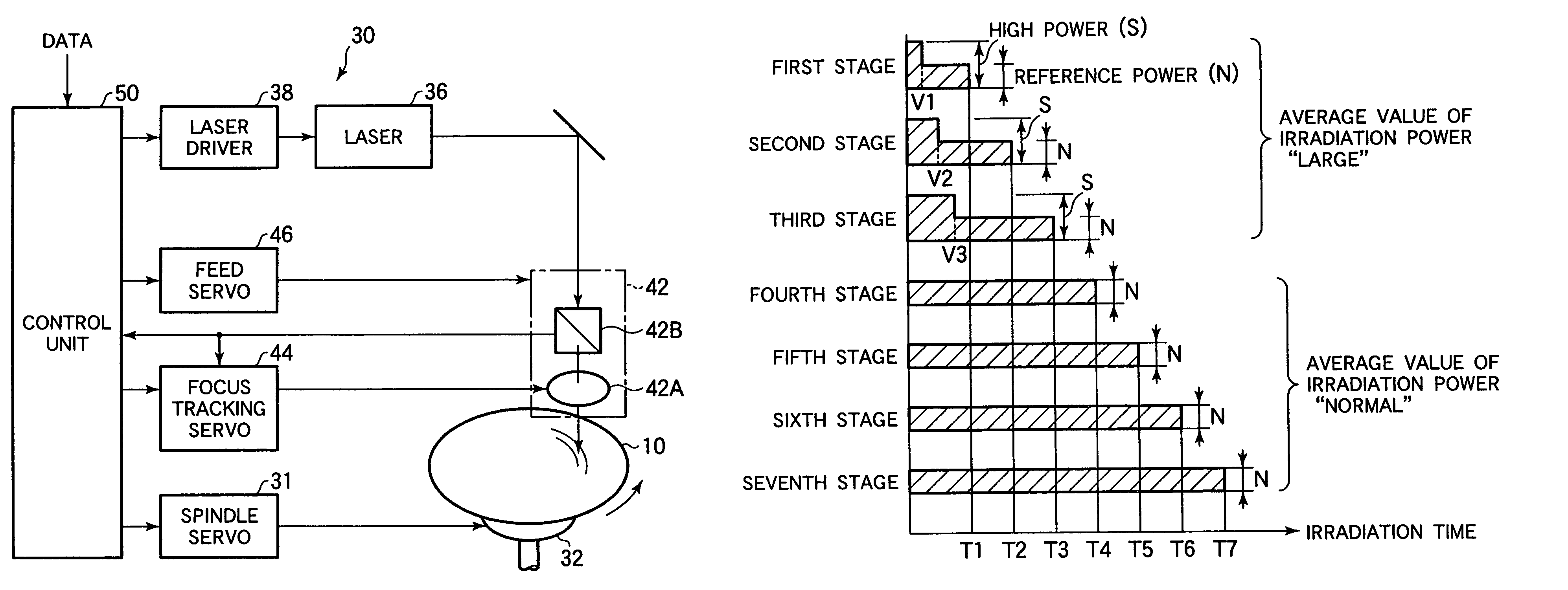
[0110]In the optical recording medium 10 and the optical recording method of this third embodiment, plural virtual recording cells 40 are continuously provided along the relative moving direction S so as to have an arbitrary unit length H along the relative moving direction to the laser beam and a unit width W perpendicular to the length H.

[0111]Moreover, as shown in FIG. 8, five stages or more irradiation times (seven stages in this embodiment) are preset with respect to the virtual recording cell 40. In this case, the stage of irradiation time includes the first stage to the final stage, which successively become long.

[0112]Further, a reference time L is set so as to become shorter than the seventh stage irradiation time T7, which is the final stage. More specifically, in this third embodiment, the reference time L is set so as to become longer than the third stage irradiation time T3 and to become shorter than the fourth stage irradiation time T4.

[0113]Of all stage irradiation ti...


PUM

PropertyMeasurementUnit
optical reflectanceaaaaaaaaaa
diameteraaaaaaaaaa
diameteraaaaaaaaaa

Abstract

An optical multi-level recording medium, having a recording layer on which a recording mark is formed by irradiating a laser beam, plural virtual recording cells being continuosly formed in a relative moving direction to the laser beam on the recording layer with an arbitrary unit length and a unit width, five stages or more irradiation times being set so that the irradiation time becomes long successively from the first to final stages, a power average value of laser beam in a specific irradiation time of the plural-stage irradiation times being set so as to become larger than a power average value of another irradiation time longer than the specific irradiation time, and recording marks being formed in the virtual recording cell and giving five stages or more different optical reflectance when the laser beam is irradiated to the virtual recording cell.

Description

BACKGROUND OF THE INVENTION[0001]1. Field of the Invention[0002]The present invention relates to an optical recording medium and method, which records information by irradiating a laser beam to a recording layer so as to form a recording mark, and in particular, to a technology of forming a plurality of recording marks having different state so as to record a data at a multi-level.[0003]2. Description of the Related Art[0004]In a conventional optical recording medium, a method has been employed such that a data is recorded by changing a length of read signal (i.e., a length of reflection signal modulation section). On the contrary, the following method has been frequently studied, more specifically, a plurality of data is recorded to each signal having the same length by changing a depth of the read signal (i.e., a modulation degree of reflection signal) at multiple stages.[0005]According to the above optical recording method, as compared with the case where a binary data is merely ...

Claims


Application Information

Patent Timeline
Patent Type & Authority Patents(United States)
IPC IPC(8): G11B7/00G11B7/244G11B7/0045G11B7/007G11B7/013G11B7/125G11B7/126G11B7/24
CPCG11B7/0045G11B7/24088G11B7/126G11B7/00456
Inventor TSUKAMOTO, SYUJI
Owner TDK CORPARATION
Why Eureka
Try Eureka