
Delay-locked loop with built-in self-test of phase margin

a delay-locked loop and self-testing technology, applied in the field of circuits for measuring the phase margin of delay-locked loops, can solve problems such as difficulties in clock synchronization and other functions commonly performed by dlls

Active Publication Date: 2006-05-09
AVAGO TECH INT SALES PTE LTD
View PDF7 Cites 36 Cited by
  • Summary
  • Abstract
  • Description
  • Claims
  • Application Information

AI Technical Summary

Benefits of technology

[0006]Another aspect of the present invention is directed to a delay-locked loop (DLL), which includes a reference input, a feedback input and a DLL output coupled to the feedback input. A phase detector is coupled to the reference input and the feedback input and has a phase control output. A charge pump is coupled to the phase control output, and a loop filter is coupled to an output of the charge pump. A main variable delay element is coupled between the reference input and the DLL output and has a first control input coupled to the loop filter. An auxiliary variable delay element is coupled in series with the main variable delay element, between the reference input and the feedback input, and has a second control input and an auxiliary delay. The auxiliary delay is variable to a critical delay at which the DLL becomes unstable. A phase margin measurement circuit generates a phase margin output ...

Problems solved by technology

Variations in the phase margin that exceed specified margins can lead to difficulties in clock synchronization and other functions commonly performed by DLLs.

Method used


Image

  • Delay-locked loop with built-in self-test of phase margin
  • Delay-locked loop with built-in self-test of phase margin
  • Delay-locked loop with built-in self-test of phase margin

Examples


Embodiment Construction

[0016]The delay-locked loop (DLL) of the present invention enables a self-test measurement of the DLL's phase margin, which can be used to verify that the DLL is operational and that the performance characteristics of the DLL are within predefined specifications. These self-test measurements can be performed with circuitry that is fabricated with the DLL on an integrated circuit as part of a Built-In Self-Test (BIST) feature for the DLL or with circuitry that is external to the integrated circuit.

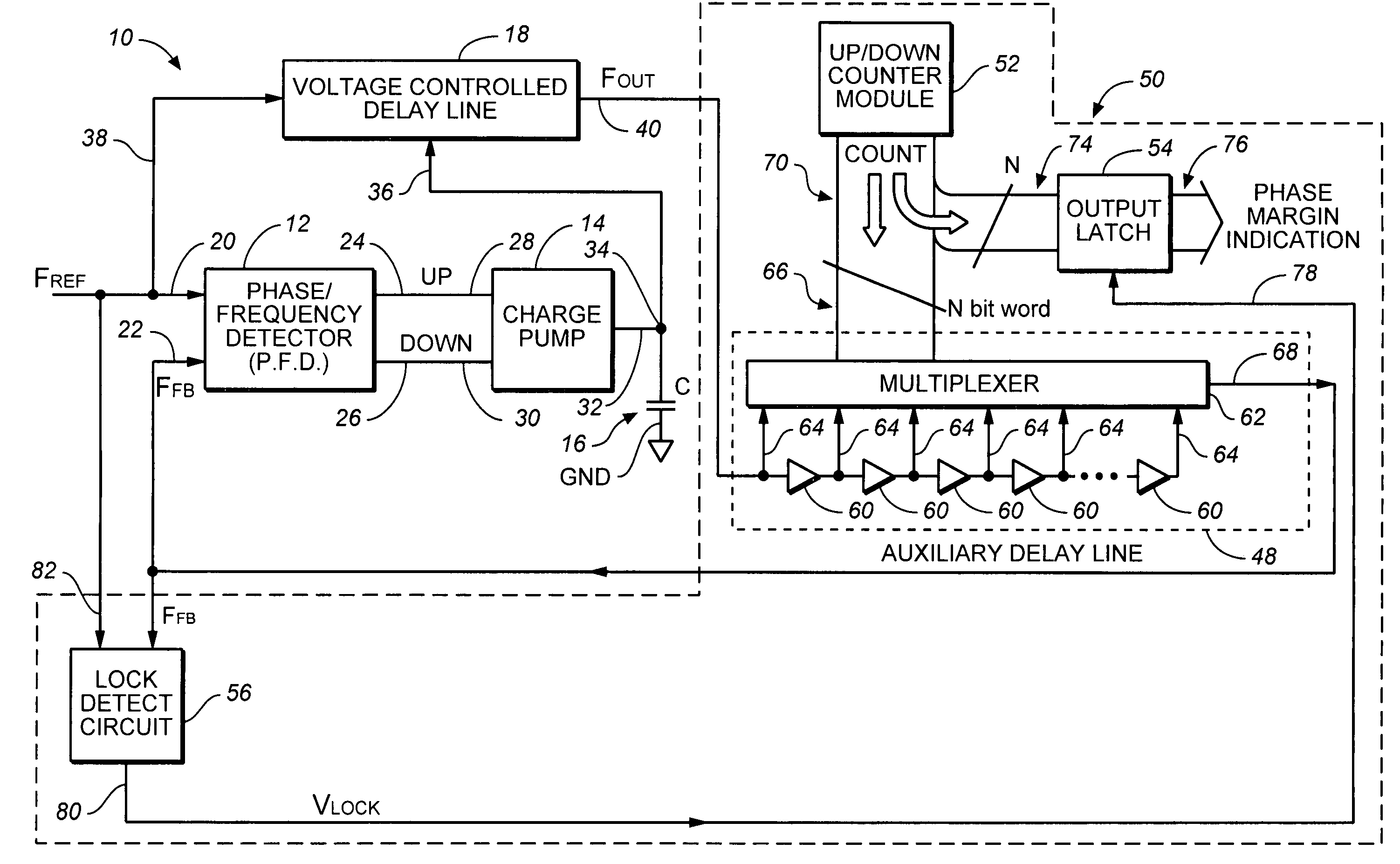
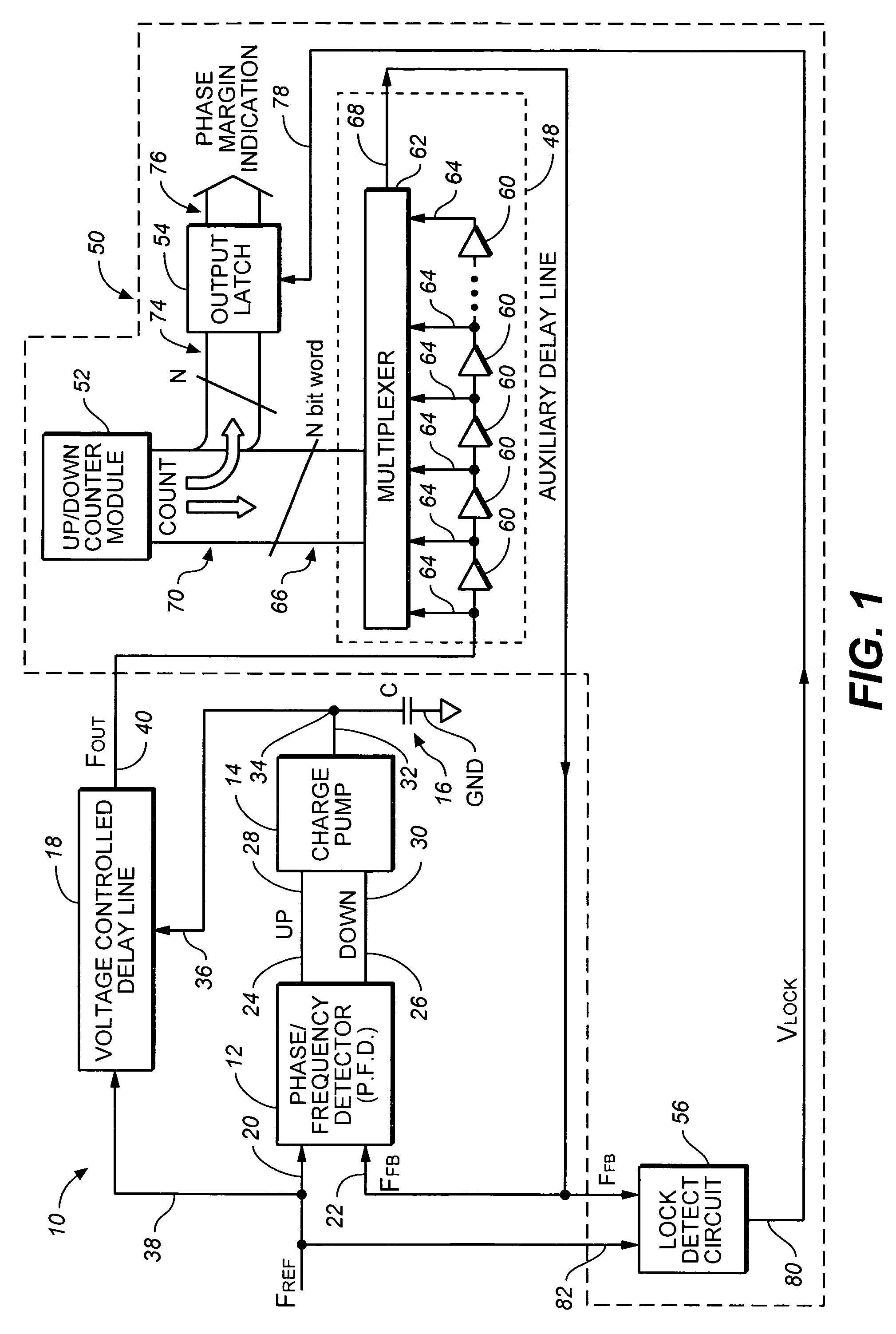
[0017]FIG. 1 is a block diagram of a delay-locked loop (DLL) 10 having a built-in phase margin measurement circuit according to one embodiment of the present invention. DLL 10 includes phase / frequency detector 12, charge pump 14, loop filter 16 and voltage-controlled delay line 18, which together form a phase detection loop. Phase / frequency detector 12 has a reference input 20, a feedback input 22 and charge pump control outputs 24 and 26. Outputs 24 and 26 are coupled to inputs 28 and 30 o...


PUM


Abstract

A method and apparatus for measuring phase margin of a delay-locked loop (DLL) is provided in which a reference clock is applied to a reference input of the DLL. An auxiliary variable delay is coupled within the DLL and is varied until the DLL becomes unstable. A phase margin output is generated as a function of a value of the variable delay at which the DLL becomes unstable.

Description

CROSS-REFERENCE TO RELATED APPLICATION[0001]Cross-reference is made to application Ser. No. 09 / 548,498, filed Apr. 13, 2000 and entitled “PHASE-LOCKED LOOP WITH BUILT-IN SELF-TEST OF PHASE MARGIN AND LOOP GAIN.”BACKGROUND OF THE INVENTION[0002]The present invention relates to semiconductor integrated circuits and, more particularly, to a circuit for measuring the phase margin of a delay-locked loop.[0003]Delay-locked loops (DLLs) are used in integrated circuits for removing phase differences between clocks, such as phase differences caused by propagation delay. A typical DLL includes a phase / frequency detector, a charge pump, a loop capacitor and a voltage-controlled delay line. The phase / frequency detector detects a phase difference between a reference clock signal and a feedback clock signal. The phase / frequency detector generates a phase control signal as a function of the phase difference and applies the phase control signal to the charge pump, which increases or decreases a vol...

Claims


Application Information

Patent Timeline
IPC IPC(8): H03D3/24H03L7/00H03L7/06H04L7/02
CPCH03L7/0812H03L7/095H03L7/0814H03L7/0816
Inventor FLANAGAN, IAN M.ROISEN, ROGER L.REDDY, DAYANAND K.CHRISTIANSEN, JOEL J.
Owner AVAGO TECH INT SALES PTE LTD
Learn More