System clock power management for chips with multiple processing modules

a technology of power management and chips, applied in sustainable buildings, instruments, high-level techniques, etc., can solve the problems of significant portion of the power used by a particular chip design and may actually be consumed by chip components other than the processor cores

Active Publication Date: 2006-05-09
NVIDIA CORP
View PDF14 Cites 279 Cited by
  • Summary
  • Abstract
  • Description
  • Claims
  • Application Information

AI Technical Summary

Benefits of technology

[0009]An object of the present invention is to provide a method and apparatus for measuring processor clock usage amongst multiple processing elements that share a common clock, and allowing for the determination of the minimum frequency that the shared clock can be run at in order to meet processing requirements for all of the processor elements.
[0010]Another object of the present invention is to provide a hardware based method and apparatus for measuring processor clock usage of a shared clock by processors in a multiprocessor system and for setting a minimum shared clock frequency which permits the processors to operate effectively while also reducing power consumed by the processors.
[0011]A further object of the present invention is to provide a software based method and apparatus for determining processor clock usage by processors operating off of a system clock and for controlling the system clock to operate at a minimum clock frequency which accommodates the operational requirements of the processors while reducing power consumed by them.
[0014]Another object of the present invention is to provide a method and apparatus for controlling a common clock for multiple processing elements based upon measured usage of the common clock by the processing elements and controlling the common clock based upon the measured usage, and which includes increasing the frequency of the common clock when it is determined that system performance may suffer because the busiest processor is not idle enough over a sample period.

Problems solved by technology

On a multi-processor system where the system clock is shared amongst multiple processing elements, the determination of the optimal system clock frequency is not so straightforward.
However, a significant portion of the power used by a particular chip design may actually be consumed by chip components other than the processor cores.

Method used


Image

  • System clock power management for chips with multiple processing modules
  • System clock power management for chips with multiple processing modules
  • System clock power management for chips with multiple processing modules

Examples


Embodiment Construction

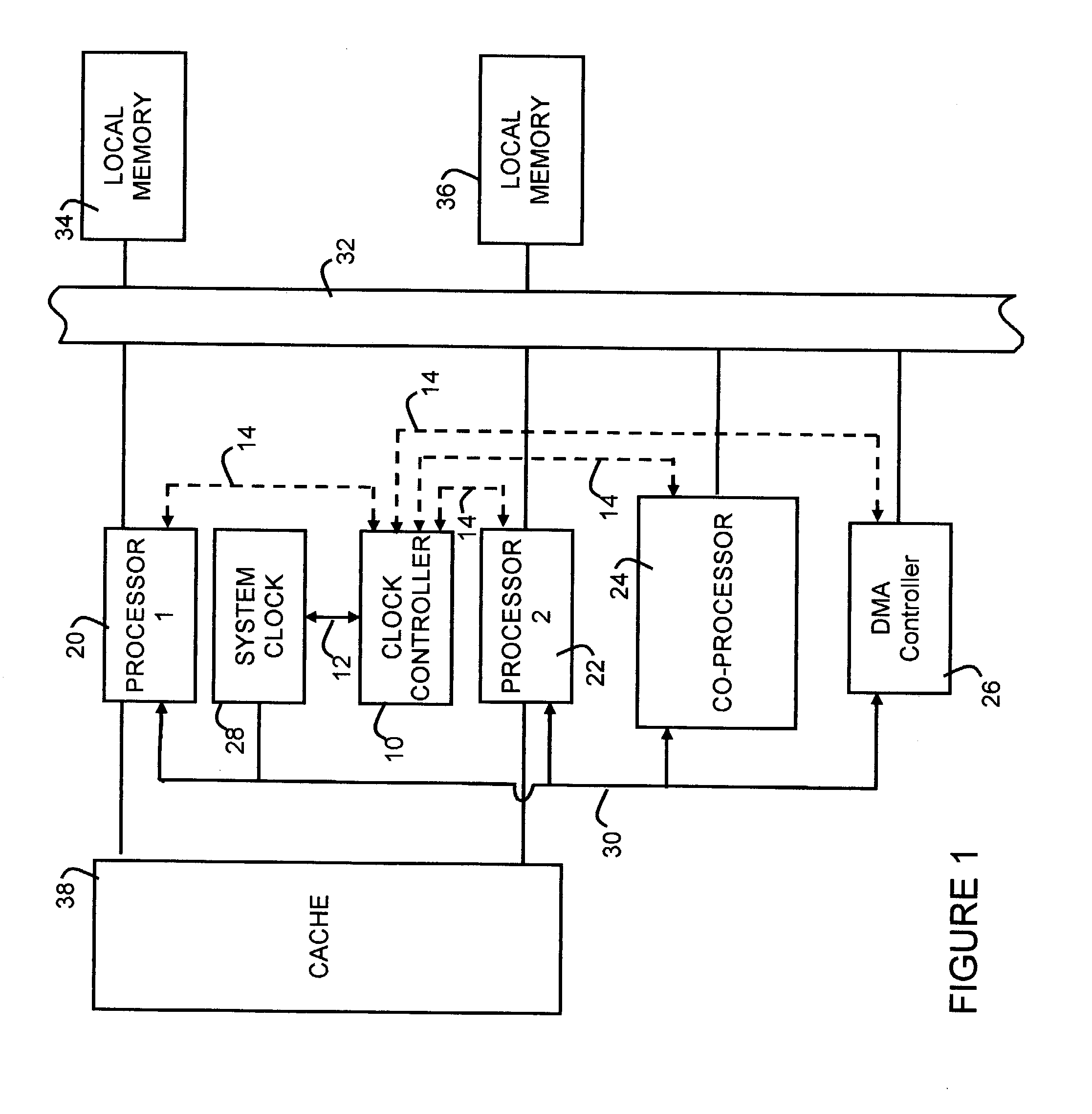
[0021]A detailed description of several example embodiments of the present invention will now be provided. FIG. 1 is a simplified functional diagram illustrating a multiprocessor system in which clock usage by several processors is measured and controlled in accordance with the present invention.

[0022]In FIG. 1, several processors 20, 22, 24 and 26, are shown sharing a system clock 28. In this example, processors 20 and 22 are processor cores; processor 24 is a co-processor; and processor 26 is a DMA controller. These processors are tied to a system bus 32, to which is also connected local memory 34 and 36. Processor cores 20 and 22 also communicate with a cache memory block 38.

[0023]A common system clock signal is supplied to processors 20, 22, 24 and 26 on line 30 from system clock 28.

[0024]Also shown in FIG. 1 is a system clock control 10 that communicates with system clock 28 via path 12, and with each of the processors 20, 22, 24, and 26 via paths 14.

[0025]There are two basic s...


PUM


Abstract

A system and method are disclosed for controlling the frequency of a common clock which is shared by a plurality of processing elements. The usage of the common clock by each of the plurality of processing elements is measured, and the common clock is controlled to have a frequency determined as a function of the measured common clock usage by the plurality of processing elements.

Description

TECHNICAL FIELD[0001]The present invention is directed generally to power management in electronic devices, and in particular to power management in multiprocessor systems.BACKGROUND ART[0002]Power management of chips that contain a single processing module by adjusting the system clock frequency is a well-known technique used by designers of portable, battery-operated computing equipment such as laptop computers, handheld computers, cell phones, etc. The system clock can be adjusted downward or upward to match the processing requirements of the applications that are currently running. Since there is only one processing module, the system clock frequency can be optimized solely for its requirements.[0003]On a multi-processor system where the system clock is shared amongst multiple processing elements, the determination of the optimal system clock frequency is not so straightforward.[0004]One approach is to simply run the system clock at its maximum frequency and gate off the clock s...

Claims


Application Information

Patent Timeline
Patent Type & Authority Patents(United States)
IPC IPC(8): G06F1/32
CPCG06F1/3228G06F1/324Y02B60/32Y02B60/1217Y02D10/00Y02D30/50
Inventor TERRELL, II, JAMES RICHARD
Owner NVIDIA CORP
Why Eureka
Try Eureka