
Method of making a two-piece super-plastic formed lightweight aluminum door

a two-piece, lightweight technology, applied in the field of vehicle doors, can solve the problems of limited door making by stamping process, inability to make stamped doors with features, and the lack of dimensional control of conventional vehicle doors made with a large number of pieces

Inactive Publication Date: 2006-05-16
FORD GLOBAL TECH LLC +1
View PDF26 Cites 20 Cited by
  • Summary
  • Abstract
  • Description
  • Claims
  • Application Information

AI Technical Summary

Benefits of technology

[0017]According to another aspect of the present invention, a vehicle door assembly is provided that comprises an aluminum super-plastic formed inner door panel having an outwardly extending perimeter flange. The door also includes an aluminum super-plastic formed outer panel having an outer perimeter flange that enco...

Problems solved by technology

Doors made by a stamping process are limited by manufacturing constraints to relatively shallow contours and are limited to the extent that feature lines may be formed in the door panels.
For example, stamped doors cannot be made with feature lines that originate in a flat surface at the middle of a panel.
Conventional vehicle doors made with a large number of pieces tend to suffer from a lack of dimensional control due to the stack up of tolerances permitted for each part.
Poor dimensional control adversely impacts vehicle craftsmanship and quality assessment target achievement.
Parts are made within a certain degree of dimensional tolerance but when additional parts are assembled together, the tolerances may accumulate making it difficult to control the final dimensional tolerances of the finished door assembly.
If thicker aluminum sheet is used, excessive splitting and cracking may occur especially in tight radius bends.
Door inner and outer panels made with 0.9 mm aluminum are too thin generally to accept mounting hardware without additional reinforcement.
Any shift in the position of the door inner relative to the door outer can result in unacceptable dimensional variation.
Adding reinforcements increases the weight of the overall door assembly.

Method used


Image

  • Method of making a two-piece super-plastic formed lightweight aluminum door
  • Method of making a two-piece super-plastic formed lightweight aluminum door
  • Method of making a two-piece super-plastic formed lightweight aluminum door

Examples


Embodiment Construction

)

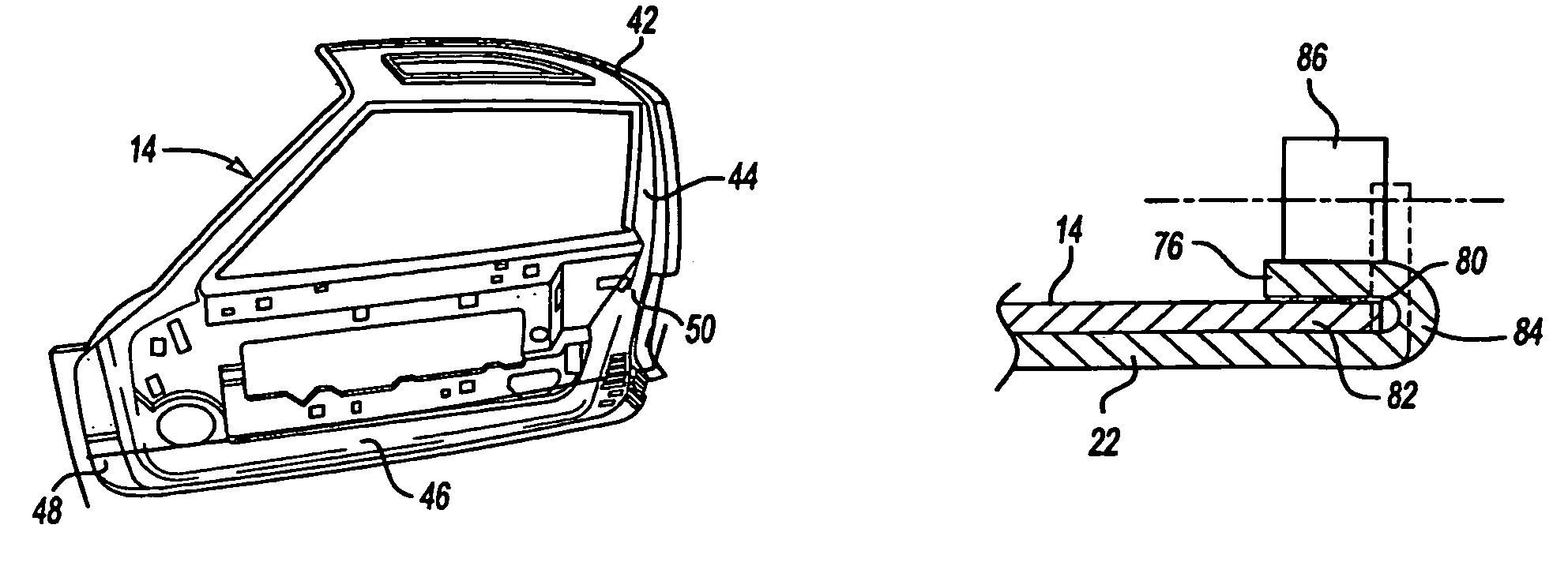
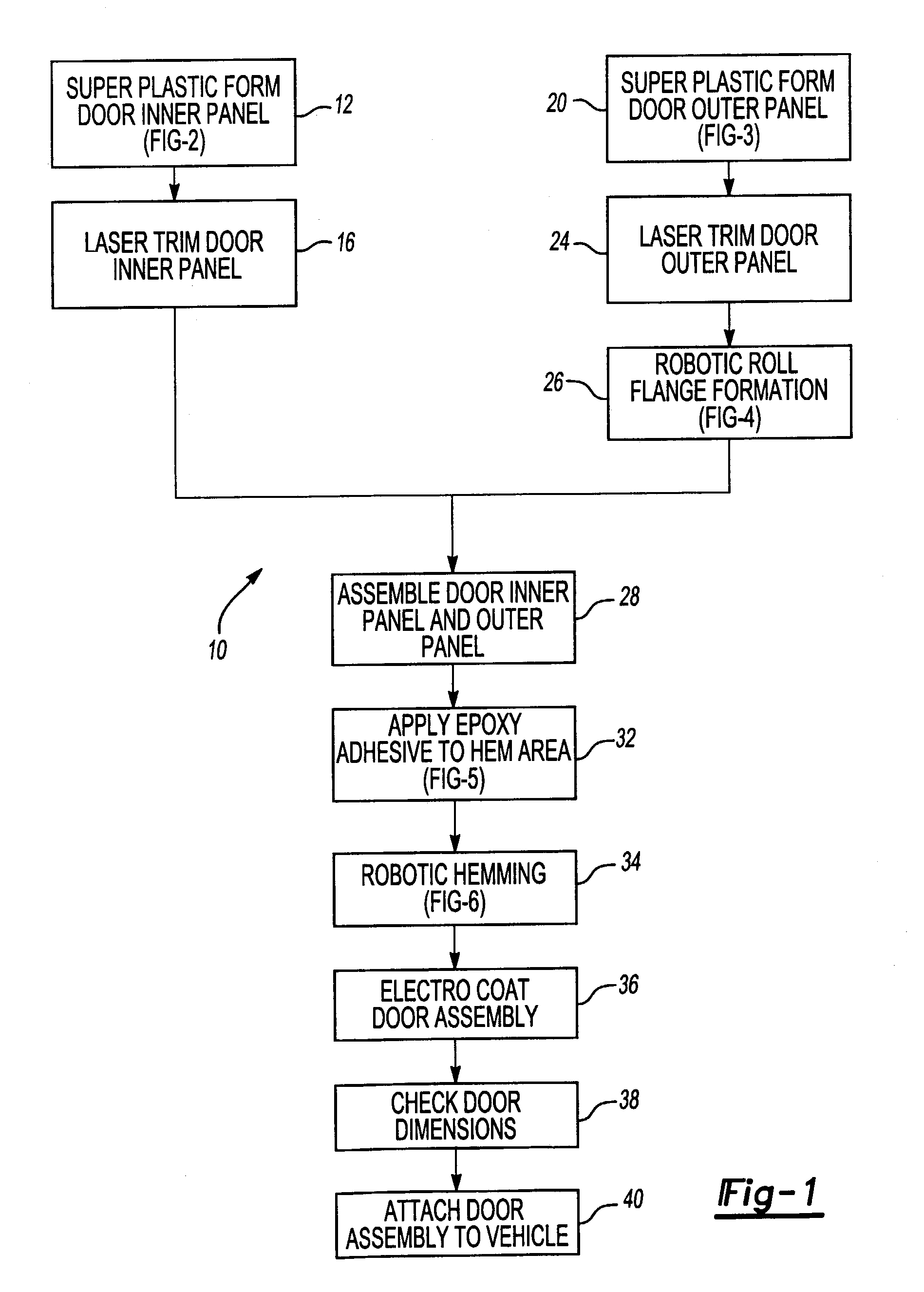
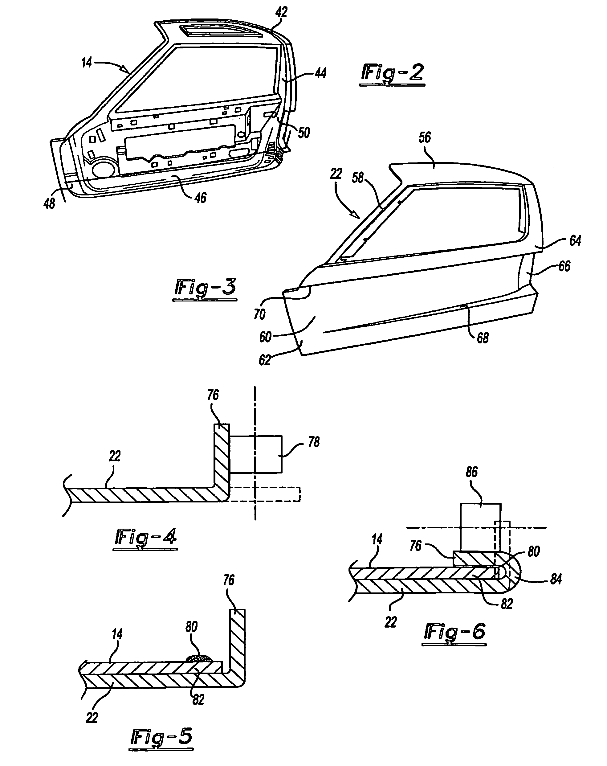
[0026]Referring to FIG. 1, the process, generally indicated by reference numeral 10, is illustrated by a flow chart. The process begins by super-plastic forming a door inner panel 14 as shown in FIG. 2. After forming, the door inner panel 14 is trimmed at 16. The trimming operation may be performed in two steps comprising a rough trim and a finished trim. The trimming operation may be performed by means of a laser trimming tool or by other trimming tools such as water jet cutting, routering or other mechanical shear or trimming tools.

[0027]In a parallel process a super-plastic forming operation is used to form the door outer panel 22 as illustrated in FIG. 3. The door outer panel 22 is trimmed, at 24, preferably with a laser trim tool, however, other methods of trimming may be used to form the outer panel 22 to its specified dimensions with a tolerance of 1 millimeter. A flange is formed preferably by a robotic roll forming machine at 26. The flange is shown schematically in FIG. 4...


PUM

PropertyMeasurementUnit
Temperatureaaaaaaaaaa
Areaaaaaaaaaaa
Strengthaaaaaaaaaa

Abstract

A method of making a vehicle door assembly by assembling a super-plastic formed inner door panel with a super-plastic formed outer panel. A flanging and roll hemming tool are used to form a hem flange to secure the outer door panel to the inner door panel. A room temperature curable two-part epoxy adhesive is used to lock the inner and outer door panels together. The epoxy adhesive is permitted to cure before the assembly is heated in electro-operations or paint ovens. Hinge and striker attachment areas are provided that are not substantially thinned or stretched during the super-plastic forming process so as to preserve the strength of the inner and outer door panels in such areas.

Description

BACKGROUND OF THE INVENTION[0001]1. Field of the Invention[0002]The present invention relates to the manufacture of vehicle doors.[0003]2. Background Art[0004]Conventional vehicle doors are generally stamped from steel blanks in a press forming line including a first drawing step followed by trimming, flanging, and piercing operations. Normally, an inner door panel and an outer door panel are formed in separate stamping operations. The inner and outer door panels are then assembled together with reinforcement bars, brackets and other components. It is not unusual for a conventional vehicle door to have as many as 20 pieces in the completed assembly.[0005]Doors made by a stamping process are limited by manufacturing constraints to relatively shallow contours and are limited to the extent that feature lines may be formed in the door panels. For example, stamped doors cannot be made with feature lines that originate in a flat surface at the middle of a panel.[0006]Conventional vehicle ...

Claims


Application Information

Patent Timeline
IPC IPC(8): B23P19/04B21D39/02
CPCB21D39/021Y10T29/49906Y10T29/49888Y10T29/49915
Inventor ZALUZEC, MATTHEW JOHNGOODNOW, FREDLAZARZ, KIMBERLY ANNKOGANTI, RAMA P
Owner FORD GLOBAL TECH LLC
Features
  • Generate Ideas
  • Intellectual Property
  • Life Sciences
  • Materials
  • Tech Scout
  • Unparalleled Data Quality
  • Higher Quality Content
  • 60% Fewer Hallucinations
Learn More