Rim sprocket for chain saw

a chain saw and sprocket technology, applied in the field of rim sprockets, can solve the problems of high scrap rate, metal in the gate becoming solidified prematurely, and occasional chipping (chipping) of a portion of the sprocket body, so as to avoid porosity, high scrap rate, and high scrap rate

Active Publication Date: 2006-05-16
OREGON TOOL INC
View PDF6 Cites 3 Cited by
  • Summary
  • Abstract
  • Description
  • Claims
  • Application Information

AI Technical Summary

Benefits of technology

[0007]Further investigation led to an attempt to reduce the metal quantity for the larger sized sprocket so as to retain the smaller portals. The configuration of the star shaped center section and the disc shaped side walls is dictated at least in part by the configuration of the saw chain being driven. The center opening is dictated by the adapter mounted to the cup that drives the sprocket. Thus, the initial attempts at reducing volume was to create channels in the side walls of the side sections. These attempts were successfull in that the metal volume was reduced, resulting in scrap rate reduction and sprockets thus produced were found to retain the desired strength. Such success inspired further attempts to reduce metal quantity and the side walls were provided with openings, in the axial direction between the sprocket teeth, and in a third stage of development the thickness of the side wall over the sprocket teeth was also reduced.

Problems solved by technology

It was determined that the higher scrap rate resulted largely due to the metal in the gates becoming solidified prematurely.
However, when enlarged, the larger stem that was formed inside the gate (following solidification of the metal) was more difficult to break away from the sprocket and resulted in occasional chipping out (chip-out) of a portion of the sprocket body.
Even further, wear life appeared to increase due to resultant harder surfaces in the stress critical areas.

Method used


Image

  • Rim sprocket for chain saw
  • Rim sprocket for chain saw
  • Rim sprocket for chain saw

Examples


Embodiment Construction

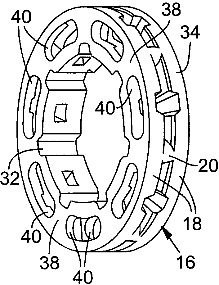
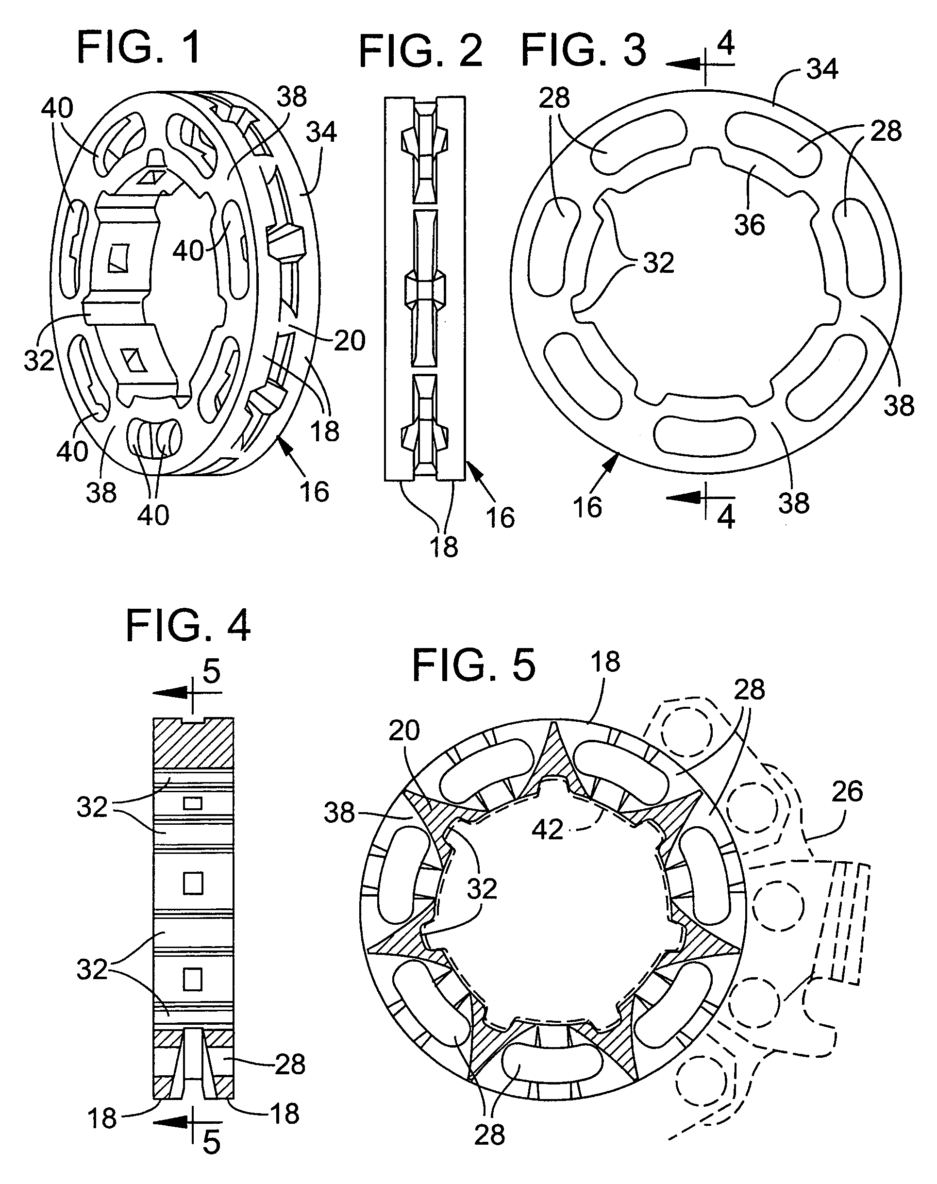
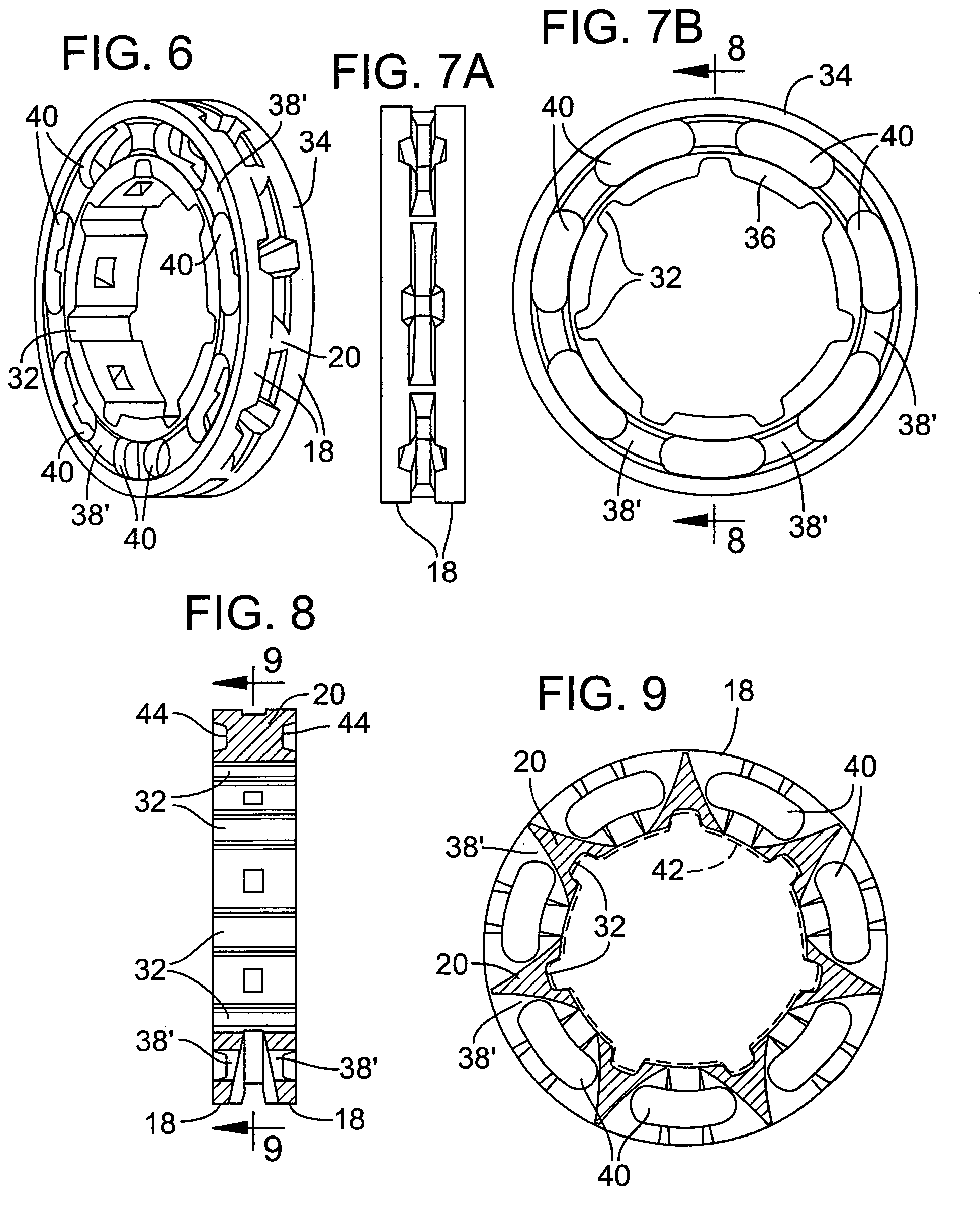
[0014]FIG. 15 illustrates a mold form 10 that is created from e.g. plastic, but also represents interconnected rim sprockets following the process of casting as will be explained. The mold form 10 is encased in a ceramic that withstands high temperatures. The encasement of ceramic is represented by dash line 15. The plastic is melted and removed, resulting in a ceramic mold having complex cavities substantially the size and shape of the mold form 10. Molten metal e.g. a steel composition, is poured down through a center sprue (as represented by arrow 12) and flows outwardly to and through portals or gates represented by stems or stem portions 14 of mold form 10 and into the outboard cavities represented by sprocket mold forms 16.

[0015]It will be noted that the stem portions 14 which represent the gates or portals of the mold casting are substantially the thickness of side walls 18 of the sprocket mold forms 16. It will be further appreciated that the molten steel (at e.g. 3,000 degr...


PUM

PropertyMeasurementUnit
massaaaaaaaaaa
weightaaaaaaaaaa
surface areaaaaaaaaaaa

Abstract

Batch casting of rim sprockets for chain saws as particularly applied to larger rim sprockets experience undesired high scrap rate resulting from porosity and chip-out. The solution is to ensure flow of molten steel throughout solidification of the molten steel in the sprocket mold while retaining molten steel portals or gates of a size that permits breakaway of portal stems. Such enhances the cooling rate of the molten steel in the sprocket mold which was found beneficial. The objective of reduced scrap rate is thus accomplished by maintaining a ratio of mass to surface area of the sprockets being cast to no greater than about 4 grams of material to each square inch of surface area and alternatively provide through bores through the rim sprockets which additionally assist in wood chip removal. This design also reduces the material content which reduces the cost and weight of the product.

Description

FIELD OF INVENTION[0001]This invention relates to a rim sprocket for driving a saw chain of a chainsaw, the saw chain comprising, e.g. center drive links connected to paired side links, certain ones of which are side cutting links, and more particularly to a structure for such rim sprocket that uses less material and is thus lighter in weight and equal or greater in strength. More particularly and / or additionally it relates to the process for producing the sprocket while reducing scrap rate.BACKGROUND OF THE INVENTION[0002]Rim sprockets can be described as having a star shaped center section (i.e., having radially extended teeth) positioned between disc shaped side walls. The spacings between the teeth circumferentially, and between the side walls laterally, define gullets that receive the drive tangs of center links of a saw chain, and the side walls further define outer peripheral support surfaces or rails which support the side links of the saw chain. The sprockets have a spline ...

Claims


Application Information

Patent Timeline
Patent Type & Authority Patents(United States)
IPC IPC(8): B27B13/00
CPCB27B17/04
Inventor ROHRICH, THOMASCHALLAPALLI, ANIL
Owner OREGON TOOL INC
Why Eureka
Try Eureka