
Radio frequency identification systems applications

a radio frequency identification and application technology, applied in the field of applications for radio frequency identification systems, can solve the problems of limiting the location affecting the accuracy of the optical bar code system,

Inactive Publication Date: 2006-05-16
3M INNOVATIVE PROPERTIES CO
View PDF239 Cites 146 Cited by
  • Summary
  • Abstract
  • Description
  • Claims
  • Application Information

AI Technical Summary

Benefits of technology

[0095]Benefits of this embodiment include that this system can help a shelver identify where to shelve an item. This can be particularly useful for the novice shelver, which may speed up the shelving operation. Once the shelver is close to the location, the device can quickly zero in on the precise shelf location. An additional a feature of the embodiments described in this section is the ability in certain of the embodiments for a user to obtain information in real time, as opposed to having to download or print out the information.
[0104]Lastly, an RFID library card may be used in conjunction with certain accounting functions performed in a library. The RFID library card would be integrated with information regarding general fees and fines that are collected in the library. These charges include overdue charges, fees for using certain equipment, copying fees, and the like. The card can act as either a debit or credit card. The data (account) can be kept on the card (updating the chip each time) or in a separate database. The main advantage, for the patron and the library, is to unify and simplify the methods by which various fees and fines are handled. Today, many of these functions are handled manually and often with some unpleasant feelings between staff and patrons. This system would allow a mostly automated method of handling these problems, reducing tension and improving staff productivity to deal with more important issues. Another option is for the patron to designate a credit card of his / hers to be associated with their RFID library card and automatically charged for fees. Thus, the library card is presented to pay fees, but it has no money directly associated with it.

Problems solved by technology

While inexpensive and effective, the optical bar code system has certain limitations.
Bar codes must be visible, which limits the locations in which they may be placed, and bar codes can easily be obscured, either accidentally or intentionally.
Also, because bar codes are often exposed to permit detection, the barcode is susceptible to damage that can result in detection failures.
These constraints of bar code systems make them undesirable or inefficient for some applications, such as marking library media.
RFID systems have succeeded in providing object identification and tracking, but are deficient in providing object security because most RFID systems operate in frequency ranges (˜1 MHz and above) in which the tag is easily defeated.
The security deficiency associated with radio frequency tags arises because they can be “shielded” by, for example, covering the tag with a hand or aluminum foil, or even placing the tag in a book.
Even battery-powered radio frequency tags may be blocked, although their range is superior and blocking would be more difficult.
Thus, objects tagged with an RFID tag may escape detection, either inadvertently or intentionally.
This greatly reduces their effectiveness as security devices.
However, none has substantially improved their performance as security tags.
Although useful for some applications, the capacitor-based tag disclosed in Narlow et al. may leak electrical charge over time, which could cause the tag to become activated unintentionally.
Although these tags have a certain utility, they still do not address the issues of enhanced security and identification.
The lower frequency tags (˜125 KHz) are moderately resistant to shielding, but have only limited radio frequency functionality due to bandwidth constraints.
They also tend to be relatively bulky and expensive to manufacture.
However, these higher frequency devices share to varying degrees the susceptibility to shielding discussed earlier.
Thus, they cannot provide the high level of security demanded in certain applications, such as a library.

Method used


Image

  • Radio frequency identification systems applications
  • Radio frequency identification systems applications
  • Radio frequency identification systems applications

Examples


example one

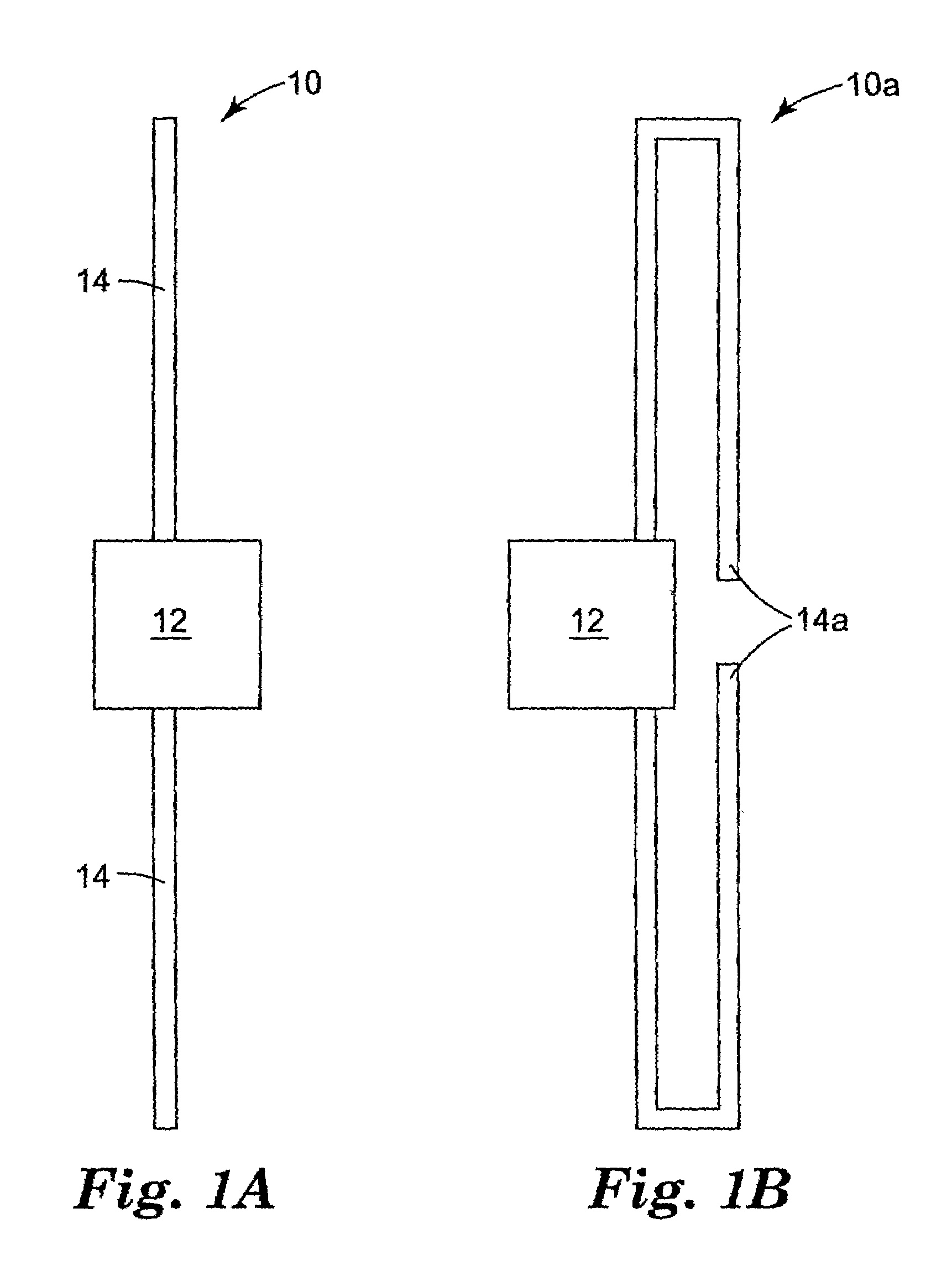
[0051]A combination tag was made in accordance with the present invention. A permalloy strip produced from an alloy available from the Carpenter Technology Corporation of Reading, Pa. under the designation “HyMu80” was attached to a test fixture manufactured by Single Chip Systems (SCS) of San Diego, Calif.

[0052]The strip measured approximately 1.6 mm (0.625 in) wide by 0.0254 mm (0.001 in) thick by 10.16 cm (4 in) long. The test fixture consisted of a standard SCS 2.45 GHz antenna connected to an LED diode. The device was designed so that upon exposure to a 2.45 GHz field strong enough to power a typical SCS RFID tag the LED would glow, providing an immediate visible confirmation of the proper operation of the power-receiving portion of the device. Upon replacing the standard SCS antenna with the prototype permalloy antenna, the LED illuminated at approximately the same field strength, confirming the successful operation of the prototype.

example two

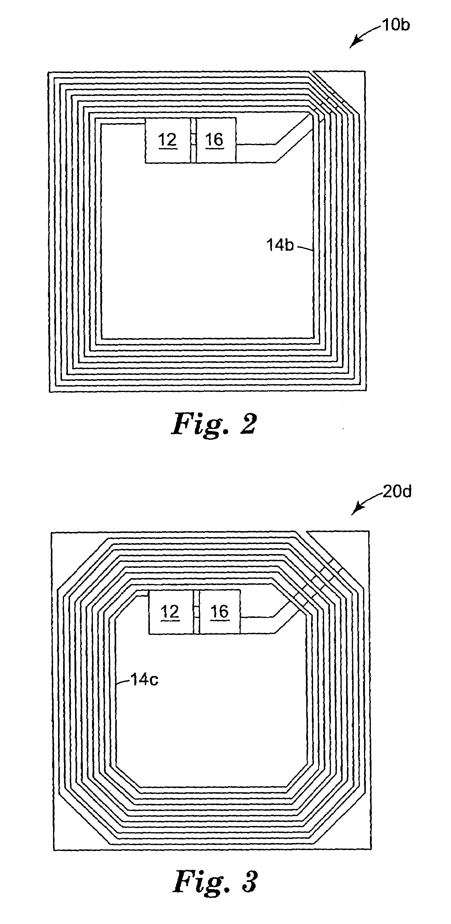
[0053]FIG. 3 illustrates another embodiment of an antenna that is believed useful with a 13.56 MHz RFID design. At this frequency, a coil-type antenna geometry is preferred. The spiral turns comprising the coil are formed from a magnetic alloy such as permalloy, either by etching (physical or chemical), die cutting, or deposition through a mask. The straight “arm” portions of the coil serve also as the magnetically responsive elements in this design. However, the reduced length of these metallic elements in this geometry limits the effectiveness of the magnetic security portion of the device. In the embodiment shown in FIG. 3, flux collection elements provided at the corners have been added to the antenna coil to overcome this limitation. The construction shown in FIG. 3 would, preferably, include a capacitor as previously described to tune the operating frequency of the antenna to the prescribed interrogation frequency.

[0054]The characteristics of the antenna described in this exam...


PUM


Abstract

The invention relates to the use of RFID systems for use with items of interest having RFID tags, such as in a library. The invention has particular applicability to determining the location, order, and other information regarding such items.

Description

RELATED APPLICATION AND INCORPORATION BY REFERENCE[0001]This patent application is a continuation-in-part of and claims priority from U.S. application Ser. No. 09 / 134,688, filed Aug. 14, 1998 now abandoned with the same title, which was assigned to the assignee of the present invention, and the contents of which is incorporated by reference herein.TECHNICAL FIELD[0002]The invention relates to applications for radio frequency identification (RFID) systems, and particularly to the use of such systems in libraries.BACKGROUND OF THE INVENTION[0003]Electronic article surveillance (“EAS”) systems detect the presence of small electronic devices placed on or in an article or carried by a person of interest, and are often used in retail or library environments to deter theft or other unauthorized removal of articles. These devices, which are commonly known as tags or markers, have in the past contained only information regarding the presence of an item. This information could be obtained by ...

Claims


Application Information

Patent Timeline
IPC IPC(8): G06F19/00G06K19/07G06F17/30G06K7/00G06K17/00G08B13/24H01Q1/24H01Q7/00H01Q9/16
CPCG06K7/0008G06K7/10079G06K17/00G06K19/07796G08B13/2457G08B13/2417G08B13/2448G06K2017/0074G06K2017/0051G08B13/24
Inventor GARBER, SHARON R.GONZALEZ, BERNARD A.GRUNES, MITCHELL B.JACKSON, RICHARD H.KAREL, GERALD L.KRUSE, JOHN M.LINDAHL, RICHARD W.NASH, JAMES E.PIOTROWSKI, CHESTERYORKOVICH, JOHN D.
Owner 3M INNOVATIVE PROPERTIES CO
Features
  • Generate Ideas
  • Intellectual Property
  • Life Sciences
  • Materials
  • Tech Scout
  • Unparalleled Data Quality
  • Higher Quality Content
  • 60% Fewer Hallucinations
Learn More