Fluid dosing device with a throttle point

a technology of flue gas and throttle point, which is applied in the direction of valve operating means/releasing devices, machines/engines, mechanical equipment, etc., can solve the problems of unavoidable leakage along the needle leadthrough, the o-ring seals used up to now do not meet the above requirements, and the requirements relating to high axial flexibility are not met when the compression strength is adequa

Inactive Publication Date: 2006-05-16
SIEMENS AG
View PDF11 Cites 25 Cited by
  • Summary
  • Abstract
  • Description
  • Claims
  • Application Information

AI Technical Summary

Benefits of technology

[0005]The object of the present invention is to provide a tight leadthrough for the valve needle in a generic fluid dosing device in particular, which achieves the required fatigue strength.

Problems solved by technology

The fatigue strength of the O-ring seals used up to now does not comply with the above requirements.
When such diaphragms are used as the leadthrough element for a valve needle through a pressurized chamber however the requirements relating to high axial flexibility are not complied with when the compression strength is adequate.
A disadvantage of this is the unavoidable leakage along the needle leadthrough.
The higher level of hydraulic loss also reduces the overall efficiency of the motor.

Method used


Image

  • Fluid dosing device with a throttle point
  • Fluid dosing device with a throttle point
  • Fluid dosing device with a throttle point

Examples


first embodiment

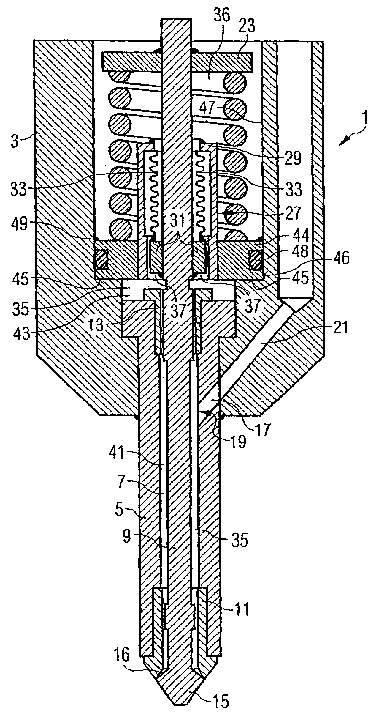
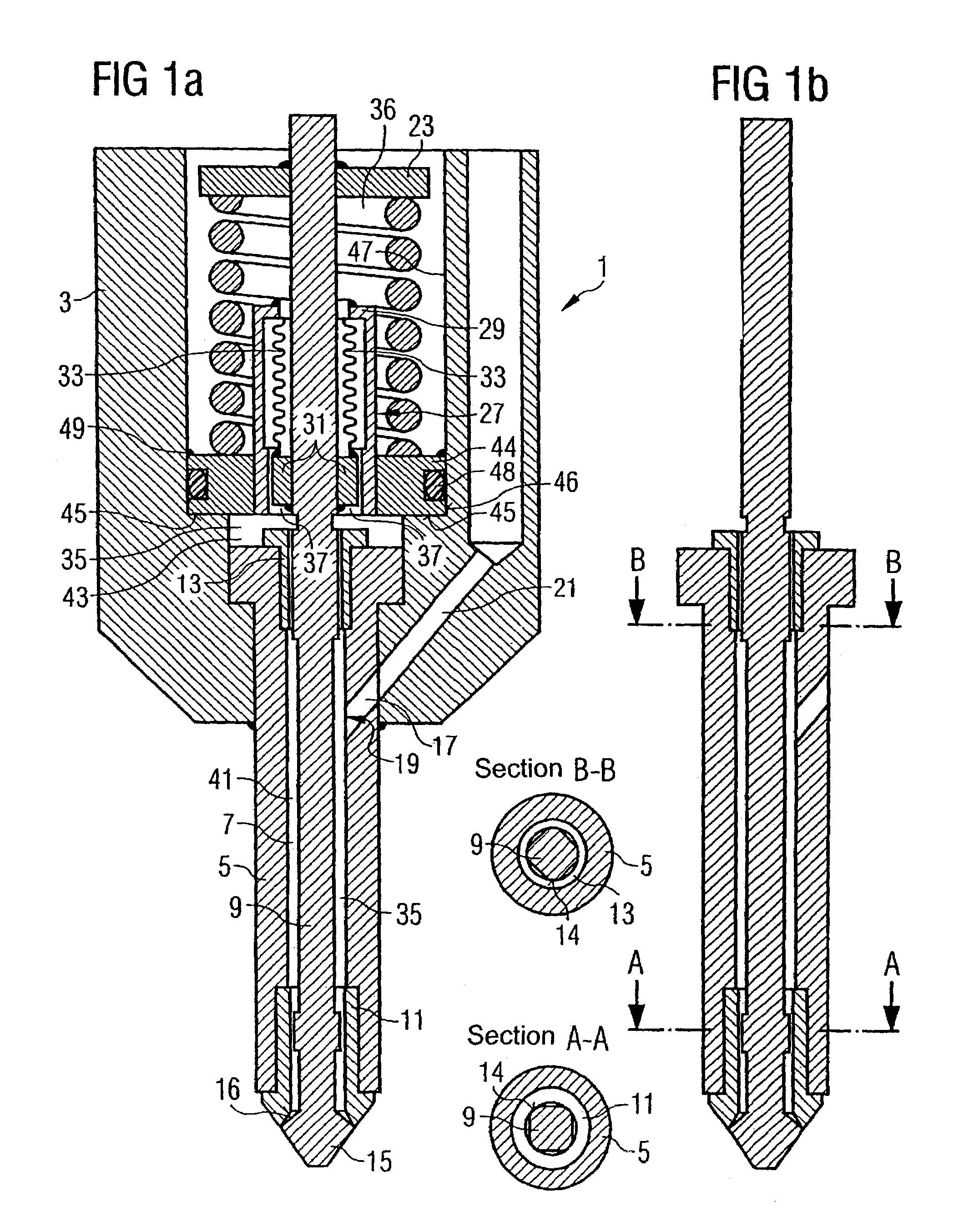
[0024]The actuator unit generally known per se is not shown for the purposes of simplicity in an injection value 1 shown diagrammatically in FIGS. 1a, b according to a The fuel injection valve 1 has a housing 3 with a central hole, in which a valve body 5 is mounted. A valve needle 9 is guided in an axially displaceable manner in a valve body hole 7 of the valve body. To this end a lower or front and upper or rear guide sleeve 11, 13 is attached to the valve body 5 in the upper and lower end sections of the valve body hole 7 and these guide sleeves create corresponding valve needle guides. The resulting narrow points are designed so that they do not impede or throttle a flow of liquid when the valve 1 opens and closes. To this end the valve needle 9 has a circumferentially projecting, rounded square cross-section according to FIGS. 1a, b (section A—A and section B—B) at both the level of the lower and upper guide sleeves 11, 13 or the two valve needle guides. The valve needle 9 wit...

third embodiment

[0030]A fuel injection valve 1 shown in FIGS. 3a, b has a second throttle point 39 in the region of the upper valve needle guide or the upper guide sleeve 13 as an alternative in place of the first throttle point according to the first two embodiments. As the fuel supply line 17 opens below the upper valve needle guide 13 into the space between the valve needle 9 and the valve body 5 or the fuel chamber 35, the fuel to be injected into this does not have to pass the upper valve needle guide 13. Therefore the upper valve needle guide can even be configured as a narrow, long cylindrical clearance fit of the valve needle 9 in the upper guide sleeve 13, as shown in section B—B in FIG. 3b. Unlike the lower valve needle guide (section A—A) the valve needle 9 here is not configured as a square but is cylindrical (section B—B). The pressure waves triggered during opening and closing processes are reflected off this second throttle point 39 and a dynamic volume exchange is throttled signifi...

fourth embodiment

[0031]According to a fuel injection valve (not shown) the throttle points 37, 39 shown in FIGS. 1 or 2 and 3 are combined in one valve. The first throttle point 37 is created by the inner and outer assembly sleeves 27, 31 and the second throttle point 39 is created by the upper guide sleeve 13 or the upper valve needle guide.

[0032]In the embodiments disclosed bellows in the form of a metal bellows were disclosed as a flexible leadthrough element. The invention is however not limited to this type of flexible leadthrough element but can also be used with other types of flexible leadthrough elements such as for example a diaphragm or a flexible plastic or rubber sleeve. The diaphragm is preferably made of metal. The diaphragm and the sleeve are stuck or welded in the same way as the disclosed metal bellows to the inner and outer assembly sleeve 27, 31.

[0033]In general the pressure in the second chamber sub-volume 43 can be adjusted by appropriate selection of the diameter of the cleara...


PUM


Abstract

A fluid dosing device for a pressurized liquid is disclosed, which comprises a chamber (35) which is supplied with pressurized liquid by means of a liquid supply line (17, 19); a valve needle (9) which is guided through the chamber (35), the first end section of said valve needle being able to be lifted and the second end section thereof forming a valve in conjunction with a valve seat disposed on the housing (3). Metal bellows (33) are provided as a leadthrough element for the first end section of the valve needle (9). The metal bellows seal the chamber in said region in a tight manner. A throttle point (37, 39) is provided between the valve needle (9) and the inner wall of the chamber between the metal bellows (33) and the mouth (18) of the liquid supply line (17) leading into the chamber.

Description

CROSS REFERENCE TO RELATED APPLICATION[0001]This application is a continuation of copending International Application No. PCT / DE01 / 04089 filed Oct. 29, 2001, which designates the United States, and claims priority to German application number 10060939.2 filed Dec. 7, 2000, and German application number 10054182.8 filed Nov. 2, 2000.BACKGROUND OF THE INVENTION[0002]The present invention relates to a fluid dosing device for a pressurized liquid with a chamber arranged in a housing, which is supplied with pressurized fluid by means of a liquid supply line and with a valve needle, which is guided through the chamber, the first end section of said valve needle being able to be lifted outside the chamber and the second end section thereof forming a valve which is connected to the housing, in conjunction with a valve seat provided on the housing.[0003]Various sealing or leadthrough elements for fluid dosing devices are known in the prior art. In cases where pressurized fuel at a pressure o...

Claims


Application Information

Patent Timeline
Patent Type & Authority Patents(United States)
IPC IPC(8): F02M61/08F02M51/06F02M61/16
CPCF02M51/0603F02M61/16F02M61/08F02M2200/16F02M51/00
Inventor FISCHER, BERNHARDGOTTLIEB, BERNHARDKAPPEL, ANDREASMOCK, RANDOLFULIVIERI, ENRICO
Owner SIEMENS AG
Why Eureka
Try Eureka