Implantable prosthesis with displaceable skirt

a technology of vascular prosthesis and skirt, which is applied in the field of tubular prosthesis, can solve the problems of internal bleeding, leakage between the vascular prosthesis and the vessel wall, and the technique, which requires open surgery, etc., and achieves the effect of active inhibition

Inactive Publication Date: 2006-05-16
LIFESHIELD SCI
View PDF22 Cites 136 Cited by
  • Summary
  • Abstract
  • Description
  • Claims
  • Application Information

AI Technical Summary

Benefits of technology

[0009]To overcome shortcomings in the prior art, and to limit Type I endoleaks, an implantable prosthesis is provided having a radially-expandable tubular body and at least one skirt extending therefrom. The skirt terminates in a peripheral edge, wherein at least portions of the peripheral edge are free and displaceable to a greater diameter than the tubular body. Thus, with the implantable prosthesis being a stent-graft used to treat an aortic aneurysm (e.g., abdominal aortic aneurysm (“AAA”)), the skirt may be used to inhibit Type I endoleaks upon its selective displacement in response to irregular aortic shaping and / or aneurysm neck expansion. The skirt may actively inhibit Type I endoleaks by forming a physical barrier against flow between the tubular body and the aortic wall. In addition, the skirt may passively inhibit endoleak formation by sufficiently restricting blood flow to allow coagulation and clot formation, which would act as a barrier against endoleakage. Endothelial cell ingrowth into the skirt may also occur providing a cellular barrier against endoleakage.

Problems solved by technology

With the collection of blood and other embolic material in the sac 1, and being subjected to hemodynamic pressure, the aneurysm A may rupture, if untreated, causing internal bleeding.
This technique, however, required open surgery.
Type I failures relate to leaks between the vascular prosthesis and the vessel wall.
A Type III failure is a mechanical failure, wherein a hole may be ripped into the prosthesis (e.g., excessive wear at a metal / non-metal (fabric or polymer) interface) or poor integrity exists at a connection, or connections, between modular components of a prosthesis, (e.g., extensions may be connected to the prosthesis to obtain improved securement in one or both of the iliac arteries IA.)
A Type IV failure relates to excessive prosthesis porosity, wherein blood seeps through the prosthesis regardless of the integrity of sealing and mechanical connections.
As can be readily appreciated, even with the successful implantation of an endovascular prosthesis, failures may occur thereafter.
It has been found that Type I failures may affect up to 5–10% of all implanted prostheses.

Method used


Image

  • Implantable prosthesis with displaceable skirt
  • Implantable prosthesis with displaceable skirt
  • Implantable prosthesis with displaceable skirt

Examples


first embodiment

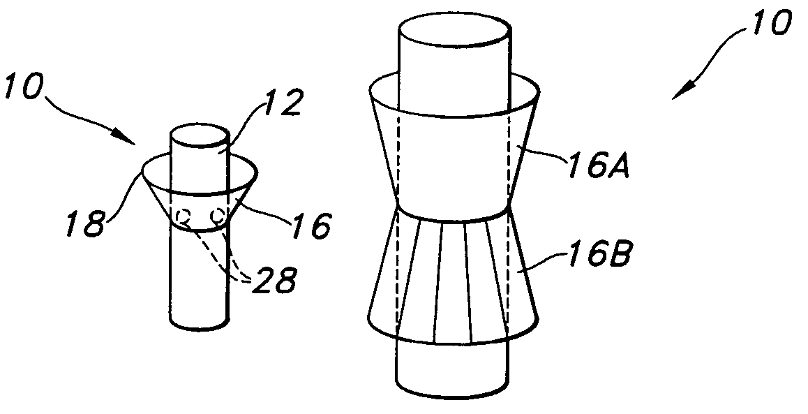
[0028]With reference to FIGS. 3a–3e, the skirt 16 is shown, which is tapered downwardly relative to the tubular body 12. Thus, with reference to FIG. 3b, the skirt 16 is intended to be tapered to a greater diameter in a direction of blood flow, as represented by the arrow. The skirt 16 is joined to the tubular body 12 at a juncture located at, or in proximity to, an upstream end of the tubular body relative to blood flow. FIGS. 3a–3c show the skirt being joined at an upstream end 20, while FIG. 3d shows the skirt 16 being spaced from the end 20. It is preferred that the skirt 16 be spaced a distance t in the range of 2–15 mm from the end 20.

[0029]In an initial state, as shown in FIG. 3a, the skirt 16 lies flat or relatively flat in overlapping a portion of the tubular body 12. With this configuration, the profile of the prosthesis 10 can be minimized in easing implantation thereof. Once implanted, such as in an aorta AA, as shown in FIG. 3c, at least a portion of the peripheral edge...

second embodiment

[0035]As a variation of the second embodiment, the first portion 24 may be trough-shaped as shown in FIGS. 4d and 4e. In an expanded, or partially expanded state, the scaffold 22 is configured such that the first portion 24 includes a trough-shaped depression which may be V-shaped, U-shaped or the like. As shown in FIG. 4e, with the skirt 16 being at least partially expanded, blood flow that bypasses the tubular body 12 (which would normally constitute endoleakage) applies hemodynamic pressure as indicated by arrow 1 into the first portion 24 which, then results in normal force applied against the sides of the trough (arrows 2). These forces cumulatively attempt to flatten the first portion 24, resulting in further radial expansion (arrow 3) of the skirt 16, and, thus, a tighter seal against a surrounding wall. With the alternative variation of FIGS. 4d and 4e, potential endoleakage is converted to increased sealing force.

[0036]With reference to FIGS. 5a–5e, a further embodiment of ...


PUM


Abstract

An implantable prosthesis is provided having a radially-expandable tubular body and at least one skirt extending therefrom. The skirt terminates in a peripheral edge, wherein at least portions of the peripheral edge are free and displaceable to a greater diameter of the tubular body. Thus, with the implantable prosthesis being a stent-graft used to treat an aortic aneurysm (e.g., abdominal aortic aneurysm (“AAA”)), the skirt may be used to inhibit Type I endoleaks upon its selective displacement in response to irregular aortic shaping and / or aneurysm neck expansion. The skirt may actively inhibit Type I endoleaks by forming a physical barrier against flow between the tubular body and the aortic wall. In addition, the skirt may passively inhibit endoleak formation by sufficiently restricting blood flow to allow coagulation and clot formation, which would act as a barrier against endoleakage.

Description

FIELD OF THE INVENTION[0001]This invention relates to tubular prostheses, including, but not limited to, endovascular grafts and stent-grafts, for maintaining patency of blood vessels and treating aneurysms (e.g., aortic aneurysms), and tubular conduits for maintaining patency in other bodily passageways.BACKGROUND OF RELATED TECHNOLOGY[0002]It is known in the prior art to use endovascular prostheses to treat aortic aneurysms (e.g., abdominal aortic aneurysms (“AAA”)). Such treatment includes implanting a stent, or stent-graft, within the diseased vessel to by-pass the anomaly. An aneurysm is a sac formed by the dilation of the wall of the artery, which may be congenital, but usually is caused by disease and, occasionally, by trauma. With reference to FIG. 1, sac 1 of aneurysm A is defined by dilated portions 2 of aorta AA. With the collection of blood and other embolic material in the sac 1, and being subjected to hemodynamic pressure, the aneurysm A may rupture, if untreated, caus...

Claims


Application Information

Patent Timeline
Patent Type & Authority Patents(United States)
IPC IPC(8): A61F2/06A61B17/11
CPCA61F2/07A61B17/11A61F2/90A61F2002/072A61F2002/075A61F2/848
Inventor ELLIOTT, CHRIS
Owner LIFESHIELD SCI
Why Eureka
Try Eureka