

Actuator and liquid discharge head, and method for manufacturing liquid discharge head
a technology of liquid discharge head and actuator, which is applied in the direction of inking apparatus, generator/motor, device material selection, etc., can solve the problems of difficult positioning of piezo-electrostrictive elements and structures, difficult to form piezo-electrostrictive film thinner, and almost 70% unavoidable piezo-electrostrictive material contraction, etc. good reproducibility and excellent piezo-electrostrictive properties
Inactive Publication Date: 2006-05-16
CANON KK
View PDF19 Cites 25 Cited by
- Summary
- Abstract
- Description
- Claims
- Application Information
AI Technical Summary
Benefits of technology
The present invention provides an actuator that can create a stable and reliable liquid discharge head with high adhesion and large displacement. The actuator uses a high-strength laminated structure containing a thin oxide film of single orientated crystal or monocrystal containing Sr and Ti, which makes it possible to perform micro processing using the semiconductor process. The actuator has a piezo-electrostrictive element with excellent piezo-electrostrictive properties, and the adhesion between the electrodes is excellent. The actuator can be manufactured with high reproducibility and stability. The invention also provides a method for manufacturing the liquid discharge head and a method for forming the actuator. The thin oxide film used as the lower electrode promotes the stable and high-quality growth of the piezo-electrostrictive film, and the adhesion between the electrodes is excellent. The actuator can be made micro miniaturized and the high-performance liquid discharge head can be created in high density.
Problems solved by technology
However, for the piezo-electrostrictive film used for the conventional piezo-electrostrictive element, it is difficult to form the piezo-electrostrictive film thinner than 10 μm, for example, because the adopted method of the film formation is such that the powered paste of PbO, ZrO2, and TiO2 is processed to be a sheet (green sheet) by molding, and after that, the sheet is sintered for the film formation.
As a result, a problem is encountered that the piezo-electrostrictive material is contracted almost to 70% unavoidably.
Under such circumstances, it is difficult to position the piezo-electrostrictive element and the structures, such as the liquid chamber and the pressure chamber, together in a high precision of several-micron order.
It is, therefore, difficult to miniaturize the actuator.
It is then difficult to obtain any good piezo-electrostrictive property.
In other words, for the piezo-electrostrictive film obtained by sintering the green sheet, there is a problem that it is difficult to obtain any sufficient piezo-electrostrictive property for discharging recording liquid if the thickness thereof becomes less than 10 μm.
Under the circumstances, it has been difficult to materialize a small liquid discharge head having the characteristics needed for discharging recording liquid sufficiently.
The density of piezo-electrostrictive film manufactured by these methods also tends to be lowered to make the micro processing thereof difficult.
Thus, it is difficult to adopt the aforesaid CVD method and the like for manufacturing a small actuator and the piezo-electrostrictive film for a liquid discharge head.
Further, with respect to the conventional art, a problem is encountered that the adherence is made lower between metallic electrodes and the piezo-electrostrictive element, which is oxide.
However, with the method of manufacture disclosed in the specification of the aforesaid laid-open paten application, it is difficult to obtain the single-orientated crystal, which is stabilized with good reproducibility or monocrystal PZT.
Further, it is impossible to obtain the PZT layer unless it is orientated on an extremely expensive monocrystal substrate, such as monocrystal MgO.
The process becomes extremely expensive unavoidably.
Further, there is a limit to the size of the MgO mono-crystal substrate to make it difficult to obtain the substrate having a large area.
However, in this specification of patent application, there is no disclosure that SrRuO3 is a crystal having single-orientation or monocrystal, and the thin oxide piezo-electrostrictive film, which should be formed on the upper part, cannot become a crystal having single-orientation or a monocrystal.
Method used
View moreImage
Smart ImageViewing Examples

Examples
example 1
[0056]Pt / Ti / / PZT(001) / / La-STO(100) / / YSZ(111) / Si(111)
example 2
[0057]Au / / PZT(001) / / La-STO(100) / / YSZ(111) / Si(111)
example 3
[0058]La-STO(100) / / PZT(001) / / La-STO(100) / / YSZ(111) / Si(111)
Login to View More PUM
 Abstract
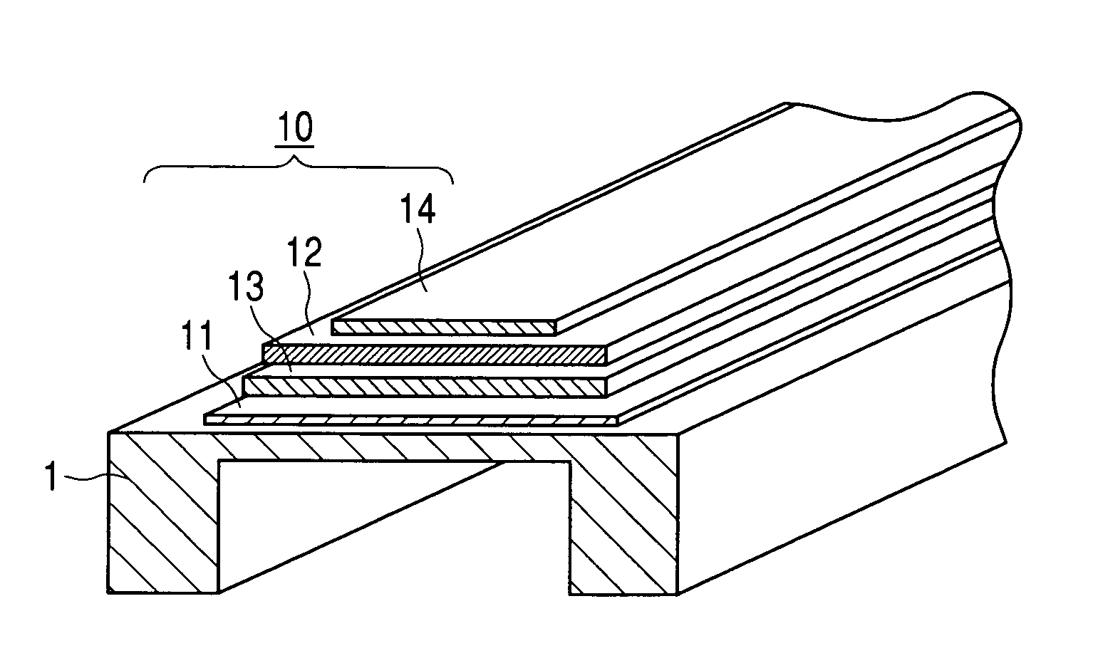
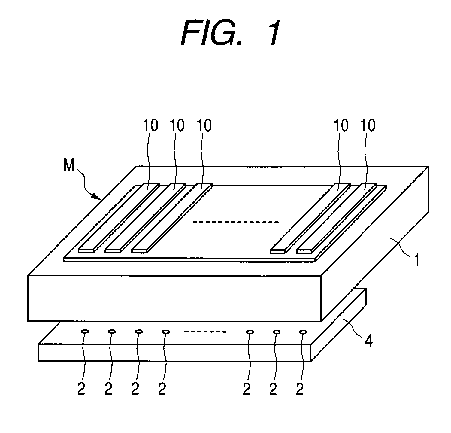
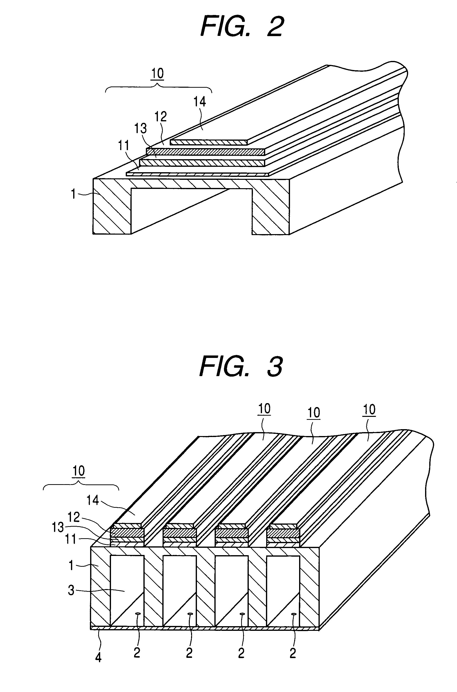
An actuator comprises a laminated structure having a vibration plate, a lower electrode, a piezoelectric element, and an upper electrode laminated sequentially on a basic element, and then, at least the lower electrode of the two electrodes is a thin oxide film doped with La of single orientated crystal or monocrystal that contains Sr and Ti. Thus, it is made possible to materialize the micro miniaturized actuator having a strong structure of lamination with high adhesion, which is capable of obtaining large displacement with sufficient durability without spoiling the piezo-electrostrictive property thereof even with the small thickness of the piezoelectric element. With the micro miniaturized actuator thus structured, it is made possible to make a liquid discharge head more precisely.
Description
BACKGROUND OF THE INVENTION[0001]1. Field of the Invention[0002]The present invention relates to an actuator used for a liquid discharge head mounted on a liquid discharge recording apparatus, as well as to a liquid discharge head. The invention also relates to a method for manufacturing a liquid discharge head.[0003]2. Related Background Art[0004]In recent years, the printer that adopts a liquid discharge recording apparatus as the printing apparatus for a personal computer and the like has been widely used for the reasons that it has an excellent printing performance with easier handling at lower costs, among some others. For the liquid discharge recording apparatuses of the kind, there are those adopting various methods; the one that discharges liquid droplets by means of the pressure wave of the bubble, which is generated by bubbling in liquid, such as ink, by the application of thermal energy; the one that enables liquid droplets to be sucked and discharged by means of electros...
Claims
Login to View More Application Information
Patent Timeline
 Patent Type & AuthorityPatents(United States)
IPC IPC(8): H01L41/047B41J2/045B05B17/04B41J2/055B41J2/135B41J2/14B41J2/16H01L21/28H01L41/08H01L41/09H01L41/18H01L41/187H01L41/22H01L41/29H01L41/316
CPCB41J2/161B41J2/1628B41J2/1629B41J2/1642B41J2/1645H01L41/314H01L41/0478H01L41/0973B41J2/1646B41J2202/03B41J2202/11H01L41/1875H10N30/878H10N30/2047H10N30/8548H10N30/074
InventorMATSUDA, TAKANORITAKEDA, KENICHIIFUKU, TOSHIHIROWASA, KIYOTAKA
OwnerCANON KK