Sensorless controller of AC motor and control method

a sensorless controller and ac motor technology, applied in the direction of motor/generator/converter stopper, dynamo-electric gear control, motor/generator/converter stopper, etc., can solve the problem of low induction voltage, low and inability to estimate a speed in a very low speed region, etc. problem, to achieve the effect of high control performance of synchronous motors

Inactive Publication Date: 2006-05-16
YASKAWA DENKI KK
View PDF13 Cites 83 Cited by
  • Summary
  • Abstract
  • Description
  • Claims
  • Application Information

AI Technical Summary

Benefits of technology

[0020]Moreover, a tenth aspect of the invention is characterized in that the magnetic flux regulator regulates a magnetic flux level into a portion in which a characteristic of the motor, that is, a magnetic saliency of a physical quantity of the motor in a high frequency region can be maintained and a high efficiency can be obtained, and the estimated error corrector corrects an estimated magnetic flux, an estimated rotor speed and an estimated rotor position error which are generated when the magnetic saliency at the high frequency is reduced.
[0023]Furthermore, a thirteenth aspect of the invention is directed to a sensorless control apparatus of an AC motor which separates a motor current into a magnetic flux component and a torque component based on an estimated magnetic flux position of a synchronous motor without using position and speed sensors and independently controls each of them, thereby implementing a high control performance of the synchronous motor, comprising means for superposing a high frequency signal on an estimated magnetic flux axis of the motor,

Problems solved by technology

Therefore, there is a problem in that a sensitivity to a fluctuation in an electric motor parameter is high so that a deterioration in a control is caused by a voltage error.
For this reason, particularly, it becomes impossible to estimate a speed in a very low speed region, including a zero speed, under a low induction voltage.
For this reason, there is a problem in that the method is apt to be influenced by a fluctuation in a parameter or an observed noise.
However, a dynamic characteristic is limited due to the high frequency signal rotating synchronously with speed of the rotations of the electric motor being used.
For this reason, there is a problem in that a sensitivity to a fluctuation in an electric motor parameter is high so that a deterioration in a control is caused by a voltage error.
In particular, they are apt to be unstable in a region having a zero speed and a zero output frequency.
However, such a method also has the following problems.
For this reason, the method cannot be used in a place in which a voltage is limited, that is, a control region is limited.
Therefore, there is a problem in that a torque vibration element such as a voltage error or a noise is generated by the superposition of the high frequency.

Method used


Image

  • Sensorless controller of AC motor and control method
  • Sensorless controller of AC motor and control method
  • Sensorless controller of AC motor and control method

Examples


first embodiment

[0066]Next, a first embodiment according to the invention will be described with reference to the drawings.

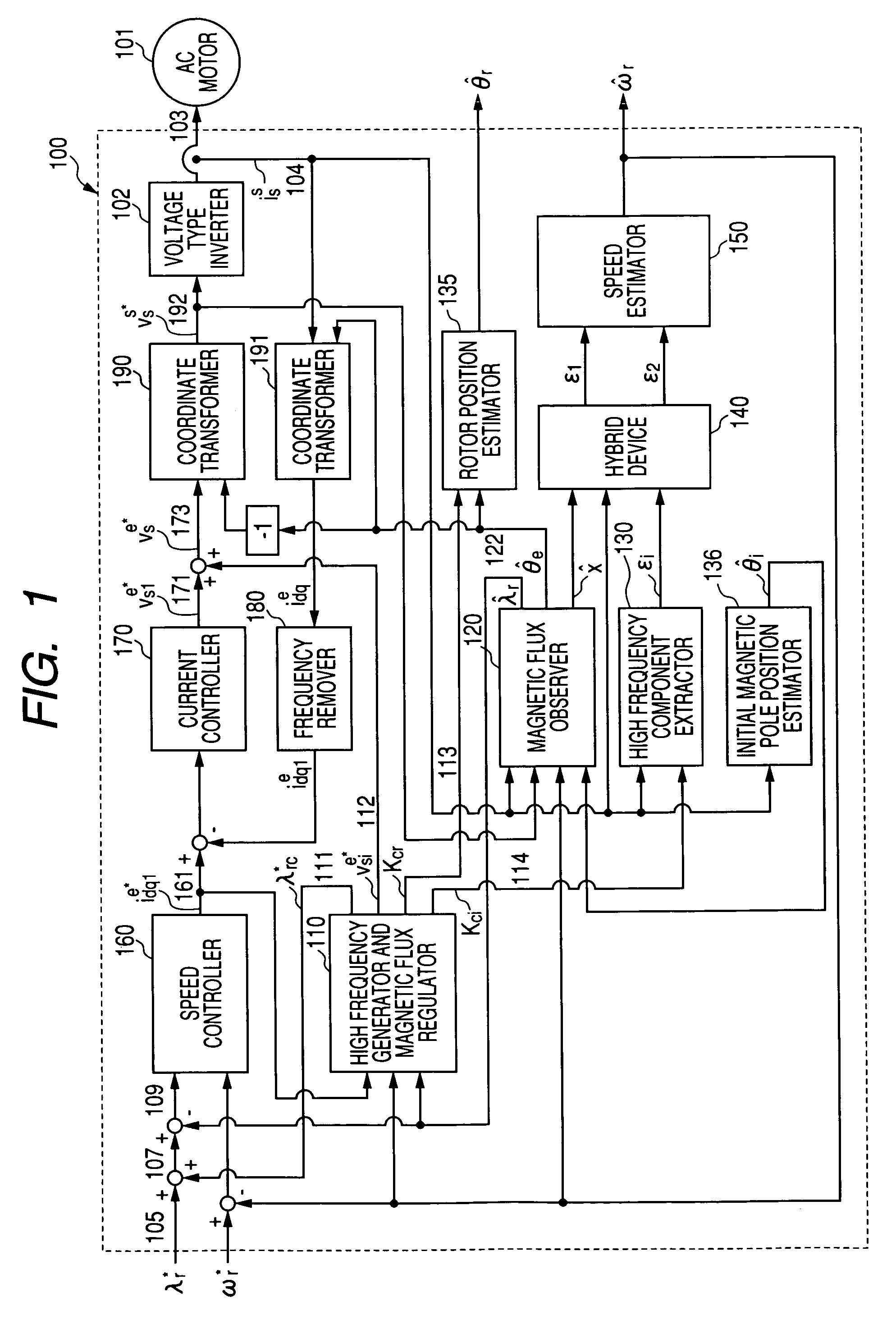
[0067]FIG. 1 is a diagram showing the structure of a sensorless control apparatus of an AC motor according to a first embodiment of the invention.

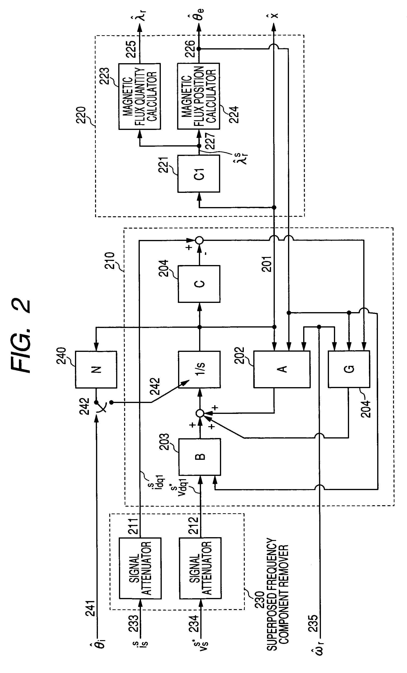
[0068]FIG. 2 is a diagram showing the details of a magnetic flux observer illustrated in FIG. 1.

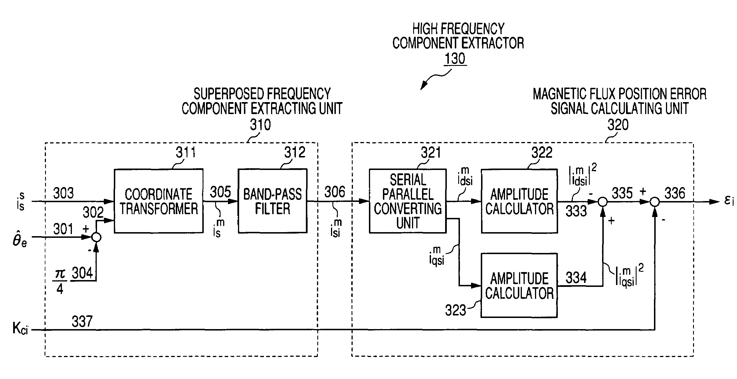
[0069]FIG. 3 is a diagram showing the details of a high frequency component extractor illustrated in FIG. 1.

[0070]FIG. 4 is a diagram showing the details of a hybrid device and a speed estimator illustrated in FIG. 1.

[0071]FIG. 5 is a diagram showing the details of a high frequency generator and a magnetic flux regulator illustrated in FIG. 1.

[0072]FIG. 6 is a diagram showing a relationship between an impedance and an operation frequency in the high frequency region of the AC motor illustrated in FIG. 1.

[0073]FIG. 7 is a diagram showing a relationship between the impedance and a load in the high frequency region of the AC motor illustrated ...

second embodiment

[0126]Next, a second embodiment according to the invention will be described with reference to the drawings.

[0127]FIG. 8 is a diagram showing the structure of a sensorless control apparatus of an AC motor according to the second embodiment of the invention.

[0128]FIG. 9 is a diagram showing the details of a high frequency component extractor illustrated in FIG. 8.

[0129]FIG. 10 is a diagram showing the details of a high frequency generator and a magnetic flux regulator illustrated in FIG. 8.

[0130]FIG. 11 is a chart showing the characteristic of a double harmonic in the case in which a voltage high frequency is superposed in an initial magnetic pole estimator illustrated in FIG. 8.

[0131]FIG. 12 is an explanatory diagram showing the initial magnetic pole estimator illustrated in FIGS. 1 and 8.

[0132]FIG. 8 is a diagram showing the structure of a sensorless control apparatus of an AC motor according to the second embodiment of the invention, illustrating a method for superposing a high fr...

third embodiment

[0159]Next, a third embodiment according to the invention will be described with reference to the drawings.

[0160]FIG. 13 is a diagram showing the structure of a sensorless control apparatus of an AC motor according to the third embodiment of the invention.

[0161]FIG. 14 is a diagram showing the details of a magnetic flux observer illustrated in FIG. 13.

[0162]FIG. 15 is a diagram showing the details of a hybrid device and a speed estimator illustrated in FIG. 13.

[0163]FIG. 16 is a diagram showing the details of a high frequency generator and magnetic flux regulator illustrated in FIG. 13.

[0164]While the example of the AC motor (synchronous motor) has been described in the above embodiments, an induction motor will be described in the embodiment. A control block shown in FIG. 13 can be implemented through a digital operation in order to drive an AC motor (induction motor) 101 in the same manner as in FIG. 1 by using a voltage type inverter 102. Moreover, the same control block can also...


PUM


Abstract

A speed control apparatus having a high frequency generator for superposing a high frequency signal on an estimated magnetic flux axis. A high frequency component extractor extracts an error signal of a magnetic flux position from a voltage or current detection signal having the same frequency component as a frequency component of the high frequency signal. A magnetic flux observer estimates a magnitude and a position of a magnetic flux. A first adaptive regulator adaptively regulates an error signal on a high frequency superposing side. A second adaptive regulator adaptively regulates an error signal on a magnetic flux observer side. A hybrid device switches the first adaptive regulator at a very low speed, the first and second adaptive regulators at a low speed and the second adaptive regulator at a high speed. A speed estimator estimates a speed from an output of the hybrid device.

Description

TECHNICAL FIELD[0001]The present invention relates to a sensorless control method for implementing stable torque, speed and position controls within all driving ranges including a region having a zero speed and a zero output frequency without using the position and speed sensors of an AC motor such as a synchronous motor or an induction motor, and a control apparatus thereof.BACKGROUND ART[0002]In an environment in which a speed sensor cannot be attached or in order to reduce the cost of a control system, conventionally, a speed sensorless control has variously been used. At present, a V / F control is employed in uses in which a speed responsiveness is not required, while a sensorless vector control is employed in uses in which the high speed responsiveness is required. The sensorless vector control serves to estimate a speed without using the position and speed sensors and to implement torque and speed controls in the same manner as a control having a sensor. A method for estimating...

Claims


Application Information

Patent Timeline
Patent Type & Authority Patents(United States)
IPC IPC(8): H02P23/00H02P25/00H02P27/00H02P6/18H02P6/06H02P6/08H02P6/182H02P6/28H02P21/00H02P21/04H02P21/06H02P21/09H02P21/14H02P21/18H02P21/22H02P21/24H02P21/26H02P21/28H02P21/34H02P23/03H02P23/07H02P23/12H02P23/14H02P23/16H02P27/04H02P29/00
CPCH02P21/04H02P6/183H02P21/141
Inventor HA, JUNG-IKIDE, KOZO
Owner YASKAWA DENKI KK
Why Eureka
Try Eureka