Ultrasonic distance measure

a technology of ultrasonic transducers and distance measures, applied in the direction of instruments, specific gravity measurement, reradiation, etc., can solve the problems of affecting the accuracy of measurement, difficult to drive the ultrasonic transducers all through the broad range, and difficult to drive with a battery, etc., to achieve high power, produce vibrations, and wide range

Active Publication Date: 2006-05-16
PANASONIC CORP
View PDF7 Cites 31 Cited by
  • Summary
  • Abstract
  • Description
  • Claims
  • Application Information

AI Technical Summary

Benefits of technology

[0013]In order to overcome the problems described above, an object of the present invention is to provide an ultrasonic distance measure that realizes high-accuracy measurements with a simple configuration.
[0039]According to the present invention, while the resonant frequency of an ultrasonic transducer is changed, a frequency-modulated ultrasonic wave is transmitted and received. That is why even if the piezoelectric element of the ultrasonic transducer has a narrow band, the ultrasonic wave can still be transmitted and received in a sufficiently broad range. Consequently, measurements can be done highly accurately without being easily affected by various fluctuations in the measuring environment including noise and wind.
[0040]Also, an ultrasonic transducer according to the present invention uses a narrow-band piezoelectric element and has its resonant or resonance frequency changed by an actuator. As a result, the piezoelectric element can be driven with small power and can produce vibrations in a broad range where the piezoelectric element should be driven with high power according to a conventional technique.

Problems solved by technology

Also, in measuring with an ultrasonic distance measure, the accuracy of measurement is affected by fluctuation of the medium or surrounding noise.
Accordingly, if the frequency of an ultrasonic wave should be modulated in a range that is broad enough to avoid the effects of noise sufficiently, then it would be difficult to drive the ultrasonic transducers all through that broad range.
However, such ultrasonic transducers need to be driven with a high output and are hard to drive with a battery, for example.
Also, if the frequency range broadens, then the ultrasonic transducer on the receiving end is likely to collect noise, which is a problem.

Method used


Image

  • Ultrasonic distance measure
  • Ultrasonic distance measure
  • Ultrasonic distance measure

Examples


embodiment 1

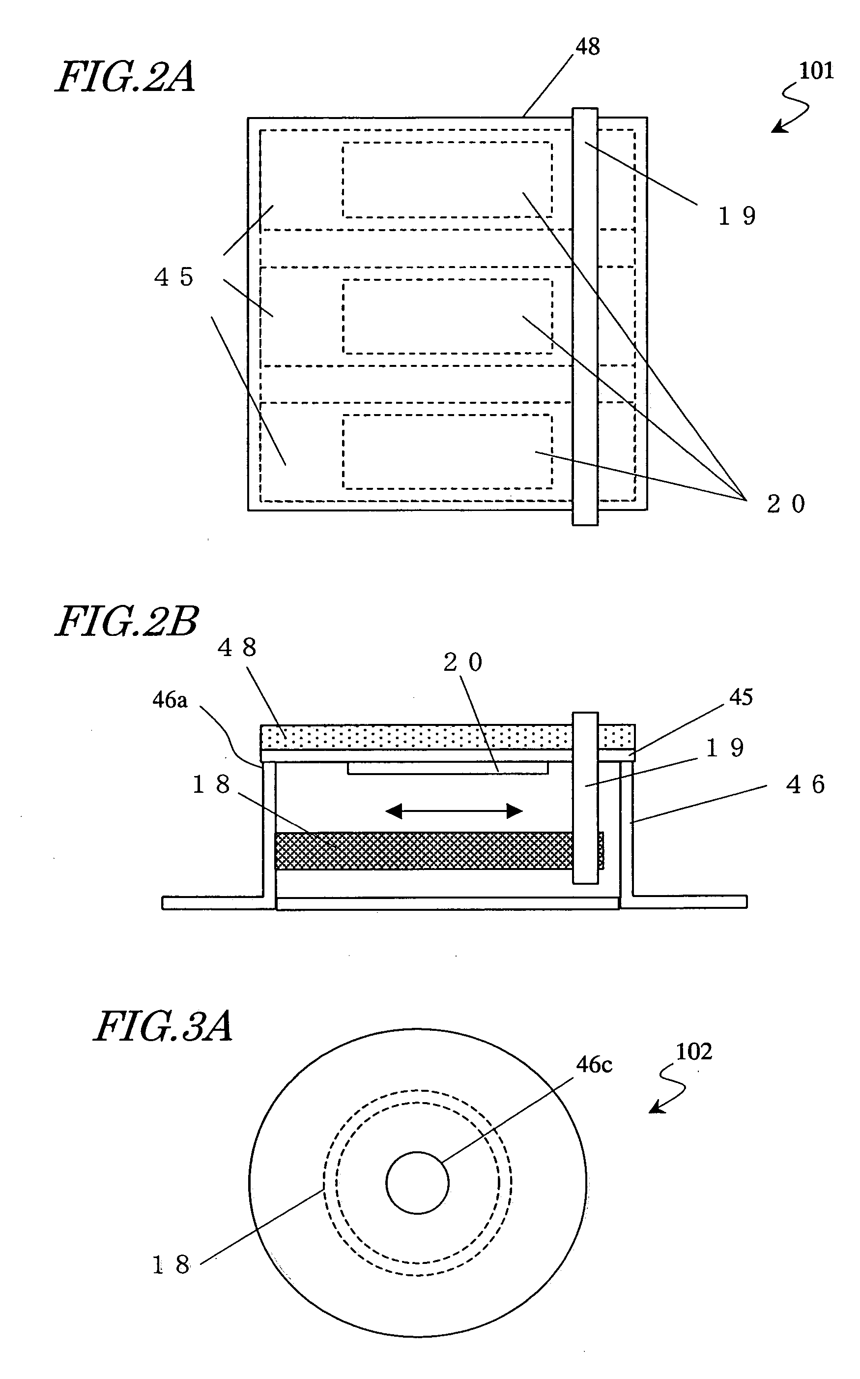
[0072]First, an ultrasonic transducer for use in an ultrasonic distance measure according to the present invention will be described. FIGS. 2A and 2B are respectively a top view and a side view of an ultrasonic transducer 101. The ultrasonic transducer 101 includes a diaphragm 45, piezoelectric transducers 20, an actuator 18 and a case 46. The piezoelectric transducers 20 are attached to the diaphragm 45 and the case 46 supports one end of the diaphragm 45 on a supporting portion 46a. A supporting plate 19 is provided near another end of the diaphragm 45. Both ends of the actuator 18 are fixed to the case 46 and the supporting plate 19, respectively. Optionally, an acoustic matching layer 48 may be provided on the surface of the diaphragm 45.

[0073]The piezoelectric transducers 20 are made of a piezoelectric ceramic such as lead zirconate titanate (PZT) and produce vibrations at a frequency in an ultrasonic range (e.g., at a frequency of approximately 20 kHz or more) upon the applica...

embodiment 2

[0119]Hereinafter, a second preferred embodiment of an ultrasonic distance measure according to the present invention will be described. As shown in FIG. 20, the ultrasonic distance measure 160 of this preferred embodiment includes a transmitting ultrasonic transducer 1, a receiving ultrasonic transducer 2, a driving section 161, a transmitting control voltage generating section 162, a receiving control voltage generating section 163 and a receiving section 164. The ultrasonic distance measure 160 further includes a timing section 169 for adjusting control timings of these sections. The timing section 169 includes: a reference clock generating section 64 for generating a clock signal as an overall reference; a trigger signal generating section 63 for sending a trigger signal to the driving section 161, transmitting control voltage generating section 162 and receiving control voltage generating section 163; and a clocking section 65.

[0120]As the transmitting and receiving ultrasonic ...


PUM


Abstract

An ultrasonic distance measure includes: transmitting and receiving ultrasonic transducers with changeable resonant / resonance frequencies; a driving section generating a frequency-modulated drive signal to drive the transducer and transmit an ultrasonic wave; a transmitting control voltage generating section for generating a control voltage to change the resonant / resonance frequency of The transducer and applying it to the transducer in transmitting the ultrasonic wave; a receiving control voltage generating section for generating a control voltage to change the resonant / resonance frequency of the transducer and applying it to the transducer when a controllable amount of time delay has passed since The drive signal was generated; and a receiving section for sensing the intensity of a signal received as the ultrasonic wave at the transducer.

Description

[0001]This is a continuation of International Application PCT / JP2005 / 007915, with an international filing date of Apr. 26, 2005.BACKGROUND OF THE INVENTION[0002]1. Field of the Invention[0003]The present invention relates to an ultrasonic distance measure for estimating the distance to an object by measuring the propagation time of an ultrasonic wave. The present invention also relates to an ultrasonic transducer for use in the ultrasonic distance measure.[0004]2. Description of the Related Art[0005]An ultrasonic distance measure transmits an ultrasonic wave toward an object and receives the ultrasonic wave that has been reflected from the object, thereby measuring the propagation time of the ultrasonic wave and calculating the distance to the object based on the propagation time. An ultrasonic wave propagates through a gas or a liquid. That is why if the velocity at which the ultrasonic wave is propagating through the medium is known, then the distance to the object in the air or i...

Claims


Application Information

Patent Timeline
Patent Type & Authority Patents(United States)
IPC IPC(8): G01R27/32G01F1/66G01F23/296G01S15/32
CPCG01F23/2962G01S15/104G01S7/527G01N2291/02836G01S5/30G01F1/66
Inventor SUGINOUCHI, TAKEHIKOSAITO, KOICHIHASHIMOTO, MASAHIKO
Owner PANASONIC CORP
Why Eureka
Try Eureka