
Device for detecting an obstacle in the opening range of a movable closure element

Active Publication Date: 2006-05-16
METZELER AUTOMOTIVE PROFILES GMBH
View PDF22 Cites 52 Cited by
  • Summary
  • Abstract
  • Description
  • Claims
  • Application Information

AI Technical Summary

Benefits of technology

[0015]The invention is based on the object of sophisticating a device of the aforementioned kind to achieve high reliability in operation and availability by relatively simple and cost-effective means.

Problems solved by technology

A disadvantage of the known device is that the distance of the electrodes forming the slot boundaries is changed by moving the side windows so that the resulting change in capacitance has to be taken into account when generating the control signal.
In this way, contact of the obstacle with the weatherseal prompts a change in the position of the sensor electrode in relation to the base electrode, resulting in a change in the capacitance.
The disadvantage with such proximity devices is that the electric field generated by the sensor electrode is subject to disruptive effects which may detriment proper functioning and reliable operation.
Thus, motion of the closure element is disruptive to the reference capacitance.
Apart from this, malfunctioning may be caused by electromagnetic interference.
Although electromagnetic compatibility (EMC) is achievable to a sufficient degree in principle by an electronic compensating circuit this makes the device unreasonably complicated.

Method used


Image

  • Device for detecting an obstacle in the opening range of a movable closure element
  • Device for detecting an obstacle in the opening range of a movable closure element
  • Device for detecting an obstacle in the opening range of a movable closure element

Examples


Embodiment Construction

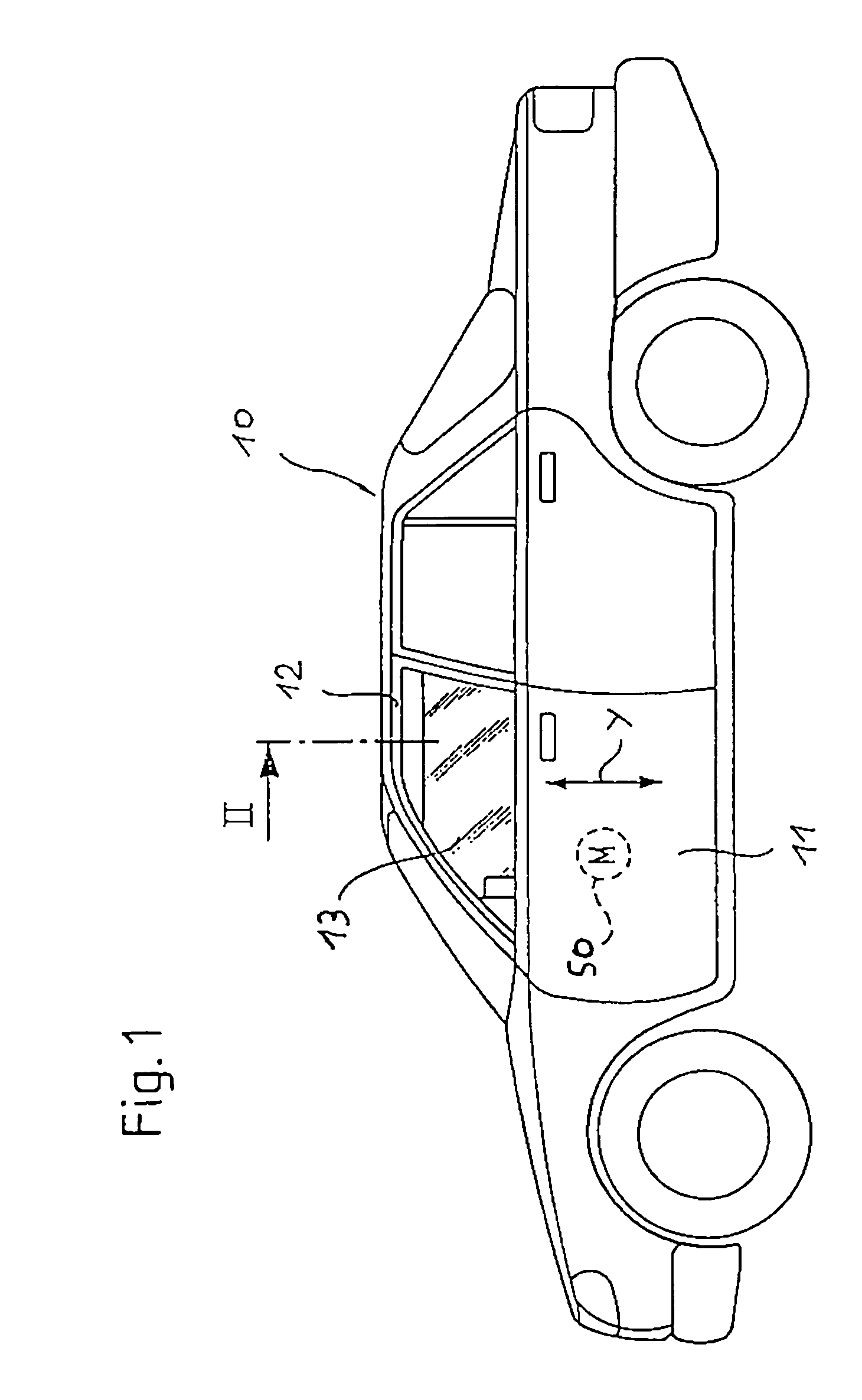
[0032]Referring now to FIG. 1 there is illustrated the motor vehicle 10 featuring a window pane 13 powered by an electric motor 50 in the region of a door 11. The window pane 13 representing a closure element is movable in the powering direction y of the electric motor 50 between an open position and a closed position.

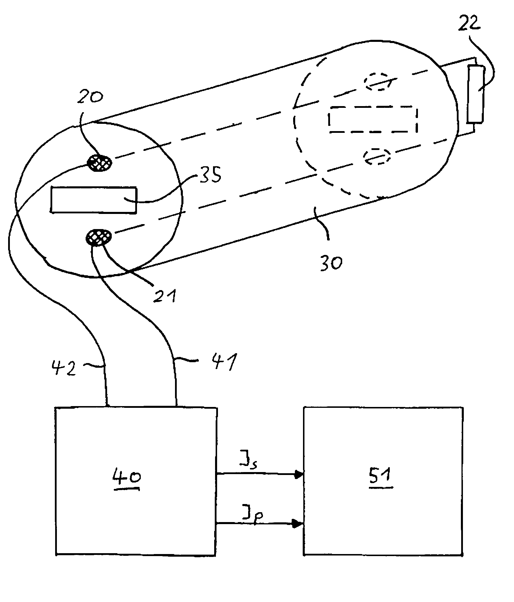
[0033]Referring now to FIG. 2 there is illustrated in more detail how the door 11 comprises a frame 12 to which a weatherseal 30 sealing the window pane 13 is secured. The weatherseal 30 made of an electrically non-conductive elastomer, for example, EPDM, comprises a fastening portion 31 defined in a channel 14 of the frame 12. For this purpose the fastening portion 31 is provided with retaining lips 32 producing a non-positive connection with the walls of the channel 14. The weatherseal 30 is provided furthermore with sealing lips 33, 34 which sealingly guide the window pane 13. In this arrangement the sealing lip 33 is in contact with a side surface of the window pan...


PUM


Abstract

A device for detecting an obstacle in the opening range of a movable closure element (13), more particularly an electrically powered window pane (13) or sunroof of a motor vehicle (10), comprises a sensor electrode (20), a base electrode (21) spaced away from the sensor electrode (20), and a control unit (40) connected to the sensor electrode (20) and the base electrode (21). The sensor electrode (20) and the base electrode (21) generate an electric field (F) in the opening range of the closure element (13) and are spaced away at a constant distance from each other in a first operational mode. The control unit (40) detects in the first operational mode a change in capacitance caused by the presence of an obstacle in the electric field (F) and providing at least one control signal (Is, Ip) for a drive (50) powering the closure element (13). The device is characterized by high reliability in operation and availability. The reason for this is that the control unit (40) provides in a second operational mode a control signal (Is) for the drive (50) powering the closure element (13) when the sensor electrode (20) comes into electrical contact with the base electrode (21).

Description

CROSS-REFERENCE TO RELATED APPLICATIONS[0001]Not applicable.STATEMENT REGARDING FEDERALLY SPONSORED RESEARCH OR DEVELOPMENT[0002]Not applicable.REFERENCE TO A “SEQUENCE LISTING”[0003]Not applicable.BACKGROUND OF THE INVENTION[0004]1. Field of the Invention[0005]The invention relates to a device for detecting an obstacle in the opening range of a movable closure element. The closure element may be for example, an electrically powered window pane or sunroof of a motor vehicle. The device is provided with a sensor electrode having a first end and a second end, a base electrode having a first end and a second end and being spaced away from the sensor electrode, and a control unit connected to the first end of the sensor electrode and the first end of the base electrode. The sensor electrode and the base electrode generate an electric field in the opening range of the closure element and are spaced away from each other at a constant distance in a first operational mode. The control unit ...

Claims


Application Information

Patent Timeline
IPC IPC(8): B60Q1/00B60J10/00E05F15/00H03K17/955
CPCB60J10/00E05F15/443E05F15/46E05Y2900/55H03K17/955E05F2015/487E05Y2800/73H03K2217/96078
Inventor REGNET, HELMUTKOPP, GUNTHER
Owner METZELER AUTOMOTIVE PROFILES GMBH
Learn More