Light track observing device

a technology of observing device and light track, which is applied in the direction of measurement device, time interval measurement, instruments, etc., can solve the problems of limiting the arrangement of apparatus or light pulse use conditions, affecting the effective light focusing, and no such observation method or apparatus is conventionally known

Inactive Publication Date: 2006-05-16
HAMAMATSU PHOTONICS KK
View PDF6 Cites 9 Cited by
  • Summary
  • Abstract
  • Description
  • Claims
  • Application Information

AI Technical Summary

Benefits of technology

[0004]Recently, it is being attempted to use the above various phenomena to, e.g., control a laser beam. However, these phenomena sometimes pose problems when an ultrashort pulse laser and the li

Problems solved by technology

However, these phenomena sometimes pose problems when an ultrashort pulse laser and the like are used.
For example, a light pulse which has caused the self-focusing effect or self-trapping effect destroys an optical element or optical material such as a lens, thereby producing defects.
Also, when a

Method used


Image

  • Light track observing device
  • Light track observing device
  • Light track observing device

Examples


first embodiment

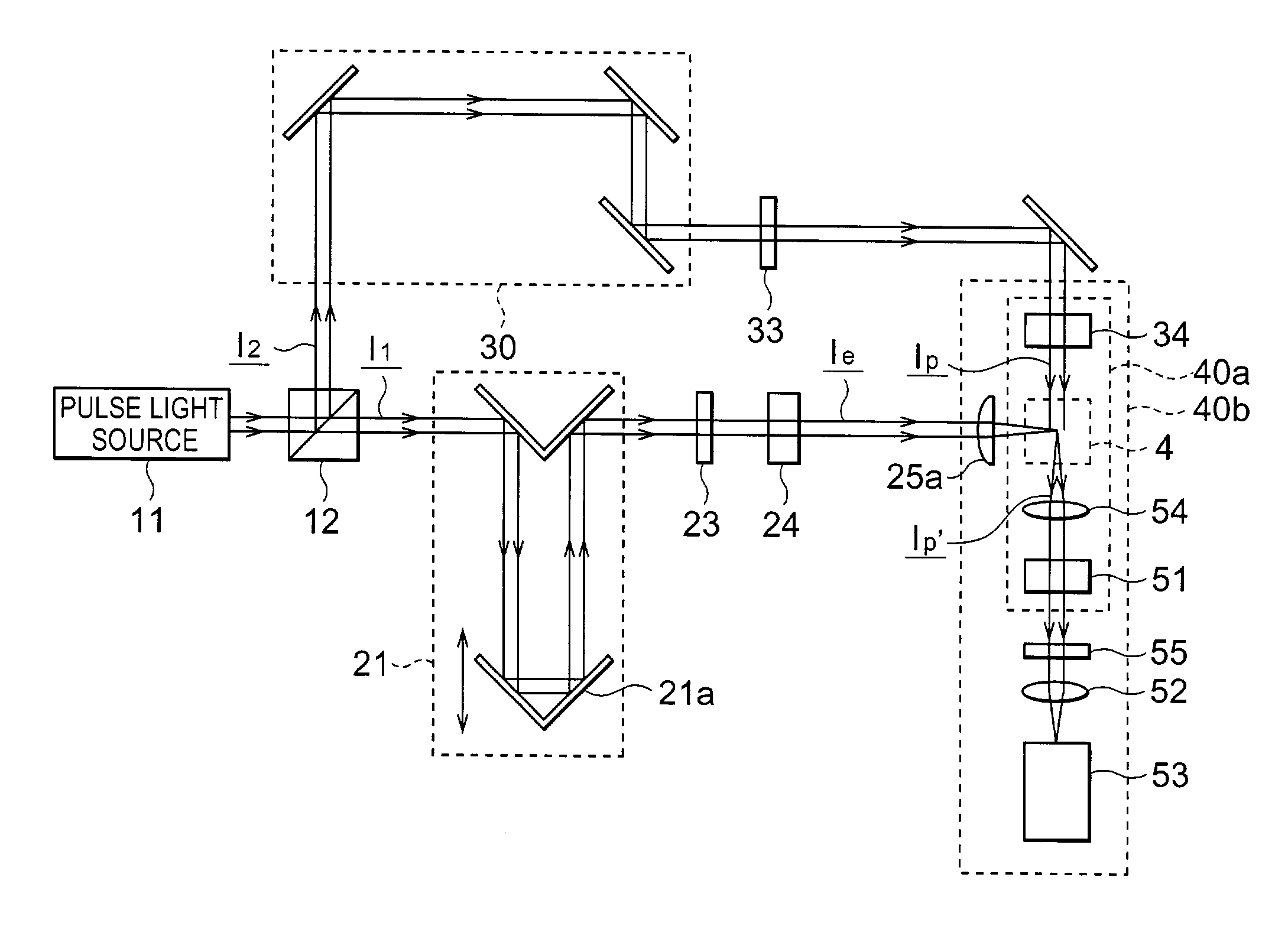
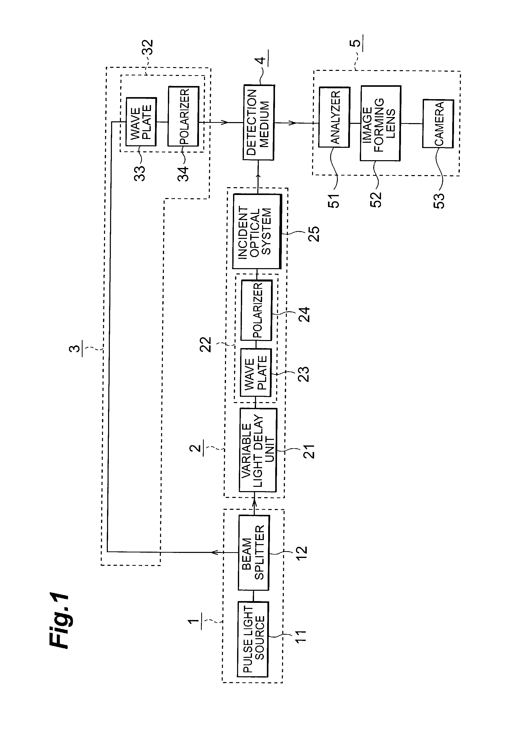
[0030]FIG. 1 is a block diagram showing the light track observation apparatus according to the present invention. The light track observation apparatus according to this embodiment comprises a light source part 1, excitation optical system 2, probe optical system 3, detection medium 4, and photodetection part 5.

[0031]The light source part 1 includes an ultrashort pulse light source 11 for generating and emitting a light pulse, and a beam splitter 12. The light pulse emitted from the ultrashort pulse light source 11 is split by the beam splitter 12 into a first light beam to be guided to the excitation optical system 2 and a second light beam to be guided to the probe optical system 3.

[0032]These first and second light beams output from the light source part 1 are guided as an excitation pulse and probe pulse, respectively, to the detection medium 4. The excitation optical system 2 forms an excitation pulse on the basis of the first light beam from the light source part 1, and feeds ...

fifth embodiment

[0090]FIG. 11 is a block diagram showing the light track observation apparatus according to the present invention. In the light track observation apparatus of this embodiment, individual parts are integrated and held by a T-shaped optical system holding mechanism 7. This optical system holding mechanism 7 is made up of a cylindrical excitation optical system holding unit 71 which is positioned around the incident axis of an excitation pulse, and holds an excitation optical system, and cylindrical probe optical system holding unit 72 which is positioned around the irradiation axis of a probe pulse, and holds part of a probe optical system and a photodetection part.

[0091]In this embodiment, a ¼-wave plate 13 is placed between a pulse light source 11 and beam splitter 12. First and second light beams split by the beam splitter 12 have circularly polarized light. In contrast, an excitation pulse polarizing means and probe pulse polarizing means include only polarizers 24 and 34, respect...

sixth embodiment

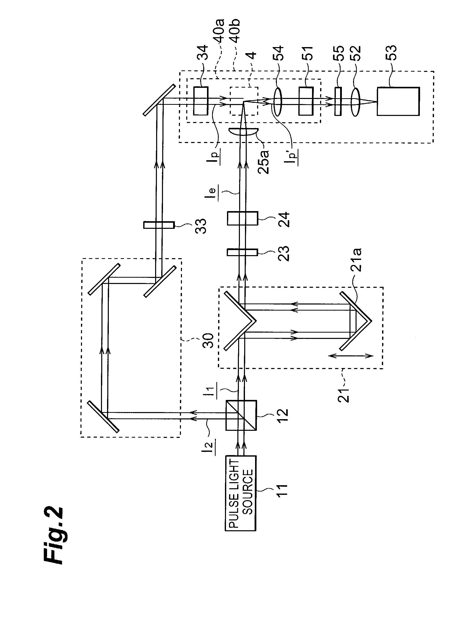
[0098]FIG. 12 is a block diagram showing the light track observation apparatus according to the present invention. In the light track observation apparatus according to this embodiment, a laser medium 4a of a pulse light source 11 which is an ultrashort pulse laser used as a light source is a detection medium. In this arrangement, an excitation pulse is a light pulse present in a laser resonator of this pulse light source 11. A probe pulse is a laser pulse output from the pulse light source 11 and split by a beam splitter 12.

[0099]With this arrangement, information pertaining to the state of a light pulse in the laser resonator can be obtained from an observation image obtained by a camera 53. By feeding this information back to the laser via a laser controller 14, the pulse laser can be optimized and stabilized. This observation can also be performed by using a dispersion compensating prism as a detection medium.

[0100]This embodiment having a laser as its object is merely an exampl...


PUM


Abstract

A light pulse from an ultrashort pulse light source 11 is split by a beam splitter 12 and guided, to a detection medium 4, as an excitation pulse and probe pulse having respective predetermined linearly polarized states by an excitation optical system 2 and probe optical system 3, respectively. A light track region which is generated in the detection medium 4 by incidence of the excitation pulse, and in which the refractive index is changed by a nonlinear optical effect, is irradiated with the probe pulse. Of components which have passed through the detection medium 4, a probe pulse component whose polarized state has changed through the light track region is detected by a camera 53 via an analyzer 51 in a photodetection part 5. This realizes a light track observation apparatus capable of directly observing the light track of an excitation pulse.

Description

TECHNICAL FIELD[0001]The present invention relates to a light track observation apparatus capable of observing the track of light such as a light pulse.BACKGROUND ART[0002]With the advance of laser technologies such as a high-intensity, ultrashort pulse laser, a nonlinear optical effect such as the optical Kerr effect, which is brought about by a laser beam having intensity larger than that of normal light, of a material and various phenomena caused by the effect are becoming problems. That is, the nonlinear susceptibility of a material with respect to a higher-order term than the second order of an electric field is smaller than that for a first-order term, so only a linear response is observed for normal light. On the other hand, the above-mentioned effect of a second-order nonlinear term or higher appears for light, such as a laser beam, having a sufficiently large intensity (electric field).[0003]Examples of this nonlinear optical effect are the self-focusing effect of light pro...

Claims


Application Information

Patent Timeline
IPC IPC(8): G01B9/02G01J11/00G04F13/02
CPCG04F13/02G01J11/00
Inventor AOSHIMA, SHINICHIROFUJIMOTO, MASATOSHIHOSODA, MAKOTOTSUCHIYA, YUTAKA
Owner HAMAMATSU PHOTONICS KK
Why Eureka
Try Eureka