Liquid-immersion objective optical system

a liquid immersion and optical system technology, applied in the field of objective optical systems, can solve the problems of insufficient examination of the behavior of molecules in the tissue and cells of the organism, low level of invasiveness to the organism, and inability to carry out long-term examination, so as to prevent relative motion, prevent image blurring, and prolong the overall length

Active Publication Date: 2006-05-16
EVIDENT CORP
View PDF13 Cites 7 Cited by
  • Summary
  • Abstract
  • Description
  • Claims
  • Application Information

AI Technical Summary

Benefits of technology

[0015]In order to examine a site deep inside the body of a small laboratory animal, such as a mouse, with minimal invasiveness, it is preferable that the diameter of the lens group in a part of the liquid-immersion objective optical system close to the object be 3 mm or less. More concretely, the part of the liquid-immersion objective optical system close to the object means a region within 8 mm from the tip of the liquid-immersion objective optical system. To observe an image viewed with the liquid-immersion objective optical system, it is necessary to connect a relay lens and CCD behind the objective lens to view the image at a position slightly separated from the organism. In order to make it difficult for the relay lens and CCD to touch the animal (for example, the head thereof), it is preferable that the overall length of the optical system, from the object plane of the liquid-immersion objective optical system to the image plane, be at least 20 mm. Also, in order to obtain bright fluorescence images and high resolution, it is preferable that the numerical aperture at the object side of the liquid-immersion objective optical system be 0.6 or higher.
[0040]The present invention affords an advantage in that it is possible to realize an objective optical system that has a narrow diameter and long overall length, that is well-corrected for chromatic aberrations, and that has a high numerical aperture, thus being suitable for in-vivo examination.

Problems solved by technology

However, since making a large incision in the organism results in a high degree of invasiveness, an excessively large strain is placed on the organism, and therefore, it is not possible to carry out examination for a long period of time.
Endoscopes generally have a small diameter, resulting in a low level of invasiveness to the organism; however, since their magnification is low, the behavior of molecules in the tissue and cells of the organism cannot be sufficiently examined.
Therefore, the resolution and brightness are insufficient.
However, the objective optical system disclosed in the above-cited reference has a drawback in that chromatic aberrations are not sufficiently corrected.
When performing fluoroscopy, particularly when using a confocal optical system, if the chromatic aberrations are not corrected, there is a problem in that the brightness of the fluorescence to be detected is low.

Method used


Image

  • Liquid-immersion objective optical system
  • Liquid-immersion objective optical system
  • Liquid-immersion objective optical system

Examples


example 1

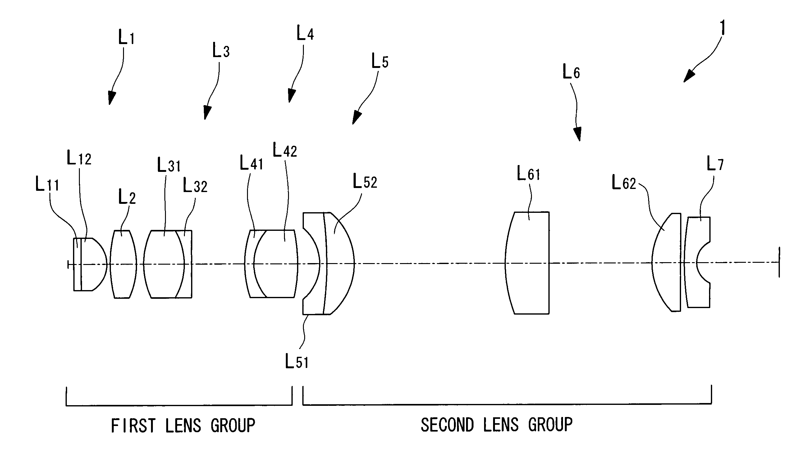
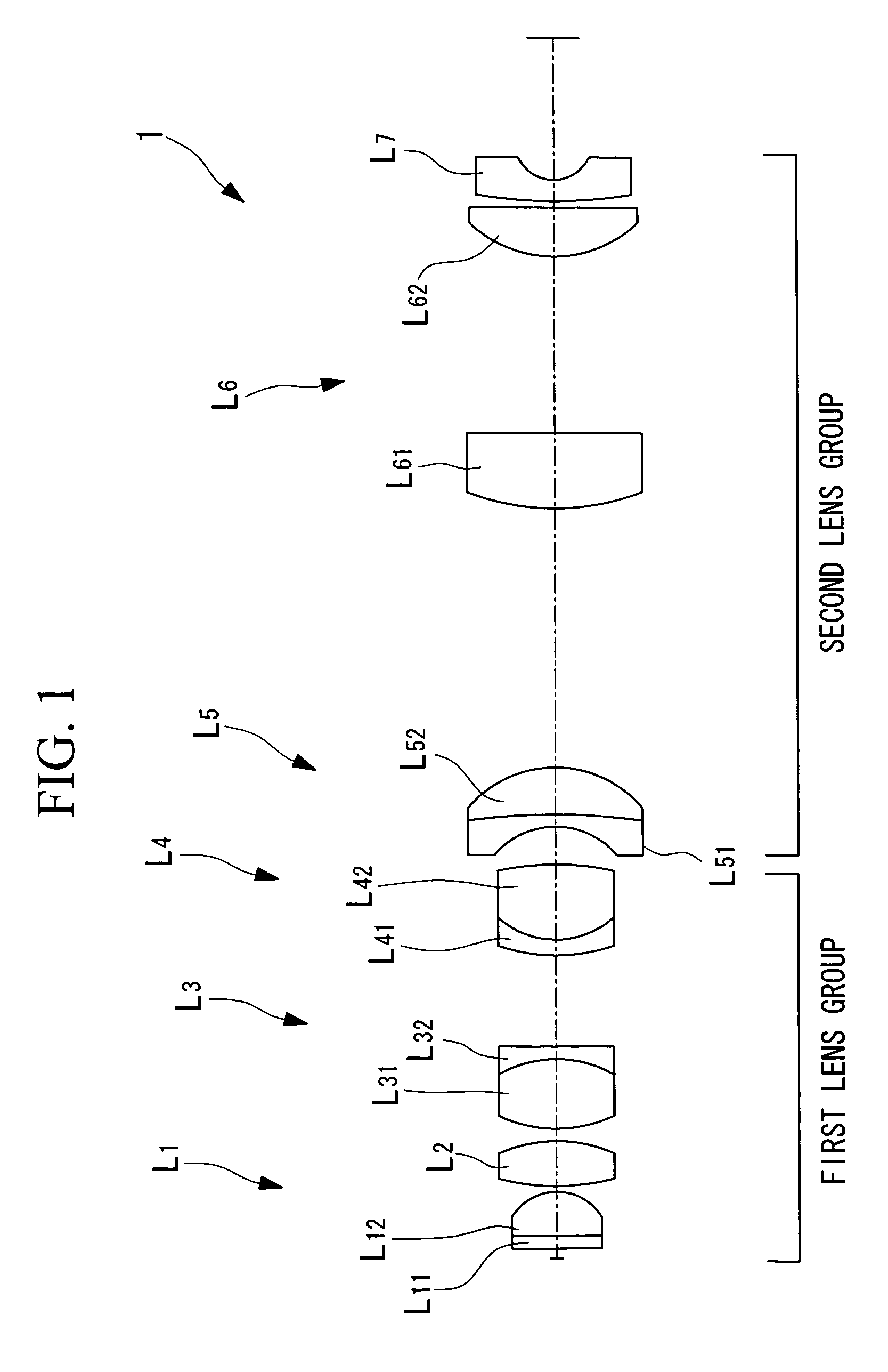
[0074]A first example of the liquid-immersion objective optical system 1 according to the embodiment described above will now be described with reference to FIGS. 3 to 5B.

[0075]As shown in FIG. 3, the liquid-immersion objective optical system 1 according to this example includes a first lens group formed of first to fourth lens components L1 to L4 and a second lens group form formed of fifth to seventh lens components L5 to L7. The first lens component L1 is formed of a parallel flat plate L11 and a plano-convex lens L12 having positive refractive power, whose convex surface faces the image-plane side. The second lens component L2 is formed of a biconvex lens with positive refractive power, having one convex surface facing the image-plane side and one convex surface facing the object side.

[0076]The third lens component L3 is a compound lens with positive refractive power as a whole, which is formed by cementing to each other a biconvex lens L31 and a negative lens L32. The fourth le...

example 2

[0088]Next, a second example of the liquid-immersion objective optical system 1 according to the above-described embodiment is described with reference to FIGS. 6 to 8B.

[0089]As shown in FIG. 6, the liquid-immersion objective optical system 1 according to this Example includes a first lens group formed of first to fourth lens components L1 to L4 and a second lens group formed of fifth to seventh lens components L5 to L7. The first lens component is formed of a parallel flat plate L11 and a plano-convex lens L12 with positive refractive power, whose flat surface faces the object side and whose convex surface faces the image-plane side. The second lens component L2 is formed of a plano-convex lens with positive refractive power, whose convex surface faces the image-plane side.

[0090]The third lens component L3 is a compound lens with positive refractive power overall, formed by cementing together a biconvex lens L31 and a negative meniscus lens L32. The fourth lens component L4 is a co...


PUM


Abstract

The invention provides a liquid-immersion objective optical system including a first lens group and a second lens group. The first lens group includes a first lens component having positive refractive power, an object side thereof being a flat surface and a convex surface thereof facing an image-plane side; a second lens component having positive refractive power, a convex surface thereof facing the image-plane side; a third lens component having positive refractive power as a whole, formed by cementing a biconvex positive lens and a negative lens; and a fourth lens component formed by cementing a negative lens and a biconvex positive lens. The second lens group includes a fifth lens component formed by cementing a lens having a concave surface facing the object side and a lens having a convex surface facing the image-plane side; a sixth lens component having positive refractive power; and a seventh lens component having negative refractive power. The focal length F1 of the entire first lens group, the magnification M of the objective optical system, the distance LT between the object plane and the image plane, and the distance LG between the object side of the first lens component L1 and the image side of the fourth lens component L4 satisfy the following conditional expressions:0.2<|M·F1 / LT|<0.450 / 2<|LG1 / LT|<0.4.

Description

BACKGROUND OF THE INVENTION[0001]1. Field of the Invention[0002]The present invention relates to an objective optical system with a high numerical aperture and a long, thin shape, and more particularly, to a liquid-immersion objective optical system that is suitable for insertion into an animal, such as a mammal, for in-vivo examination.[0003]This application is based on Japanese Application No.2004-199632, the content of which is incorporated herein by reference.[0004]2. Description of Related Art[0005]Conventional methods include those in which a dye or fluorescent marker is attached to particular molecules, tissue, or cells, which are then examined using a fluorescence microscope, a confocal laser-scanning microscope, or the like, to observe the behavior of the molecules inside the cells or tissue of a living organism. Since the behavior of molecules in the body of a live mammal, such as a mouse, may differ from that in cultured cells, it is usual to carry out in-vivo examination...

Claims


Application Information

Patent Timeline
Patent Type & Authority Patents(United States)
IPC IPC(8): G02B21/02
CPCG02B21/33
Inventor HIRATA, TADASHI
Owner EVIDENT CORP
Why Eureka
Try Eureka