Power converter with ripple current cancellation using skewed switching techniques

a technology of ripple current and power converter, applied in the direction of dc-ac conversion without reversal, power conversion system, electrical apparatus, etc., can solve the problems of inverter conversion efficiency, performance parameter, maximum switching frequency, etc., to achieve optimum ripple current cancellation, performance advantages increase, cost, weight and volume of inductive and capacitive filter components are substantially reduced

Inactive Publication Date: 2006-05-16
SCHNEIDER ELECTRIC SOLAR INVERTERS USA
View PDF6 Cites 53 Cited by
  • Summary
  • Abstract
  • Description
  • Claims
  • Application Information

AI Technical Summary

Benefits of technology

[0005]The invention is an electrical power converter using multiple, high frequency switching elements where the individual switching elements are operated in a synchronous, typically fixed-frequency, time-skewed arrangement to provide optimum ripple current cancellation. By skewing the switching times on paralleled power bridges, the cost, weight and volume of inductive and capacitive filter components are substantially reduced. The performance advantages increase with the number of power bridges used.
[0006]The invention also supports inverter system designs that use modular bridge assemblies. Product reliability is enhanced and engineering development costs are reduced when a wide range of inverter products can all be built with different combinations of the same, lower power, modular, functional block.
[0007]The primary benefit of this invention is the accelerated maturation and commercialization of distributed energy systems. These systems include renewable generator sources such as photovoltaics, wind turbines and micro-hydro, quasi-renewable sources such as fuel cells, micro-turbine and advanced batteries as well as traditional generators such as gensets and lead-acid batteries. Specific applications include green power generation, grid support and peak shaving.

Problems solved by technology

This adapted technology falls short of meeting critical requirements for commercially viable distributed energy systems.
The inverter conversion efficiency, however, is not a performance parameter that can be traded off for smaller magnetic components because the cost of the “green” energy, from a photovoltaic array, fuel cell or wind turbine is of such high value.
In DE inverters with power ratings greater than 10 kW, typically the switching and diode recovery losses of the IGBT power switches limit the maximum switching frequency, for a given conversion efficiency.

Method used


Image

  • Power converter with ripple current cancellation using skewed switching techniques
  • Power converter with ripple current cancellation using skewed switching techniques
  • Power converter with ripple current cancellation using skewed switching techniques

Examples


Embodiment Construction

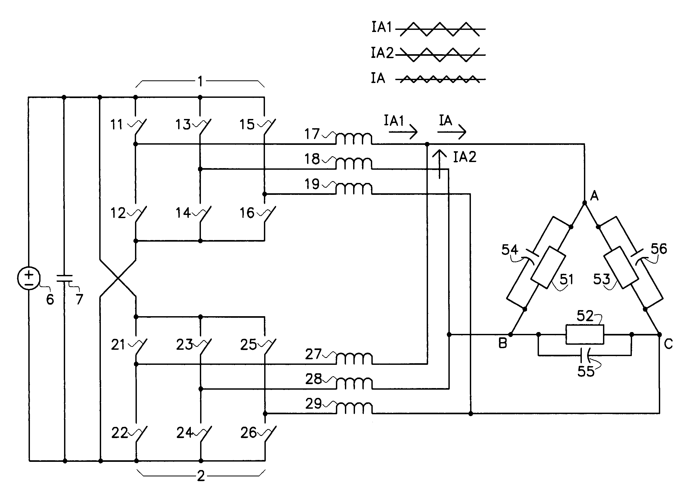
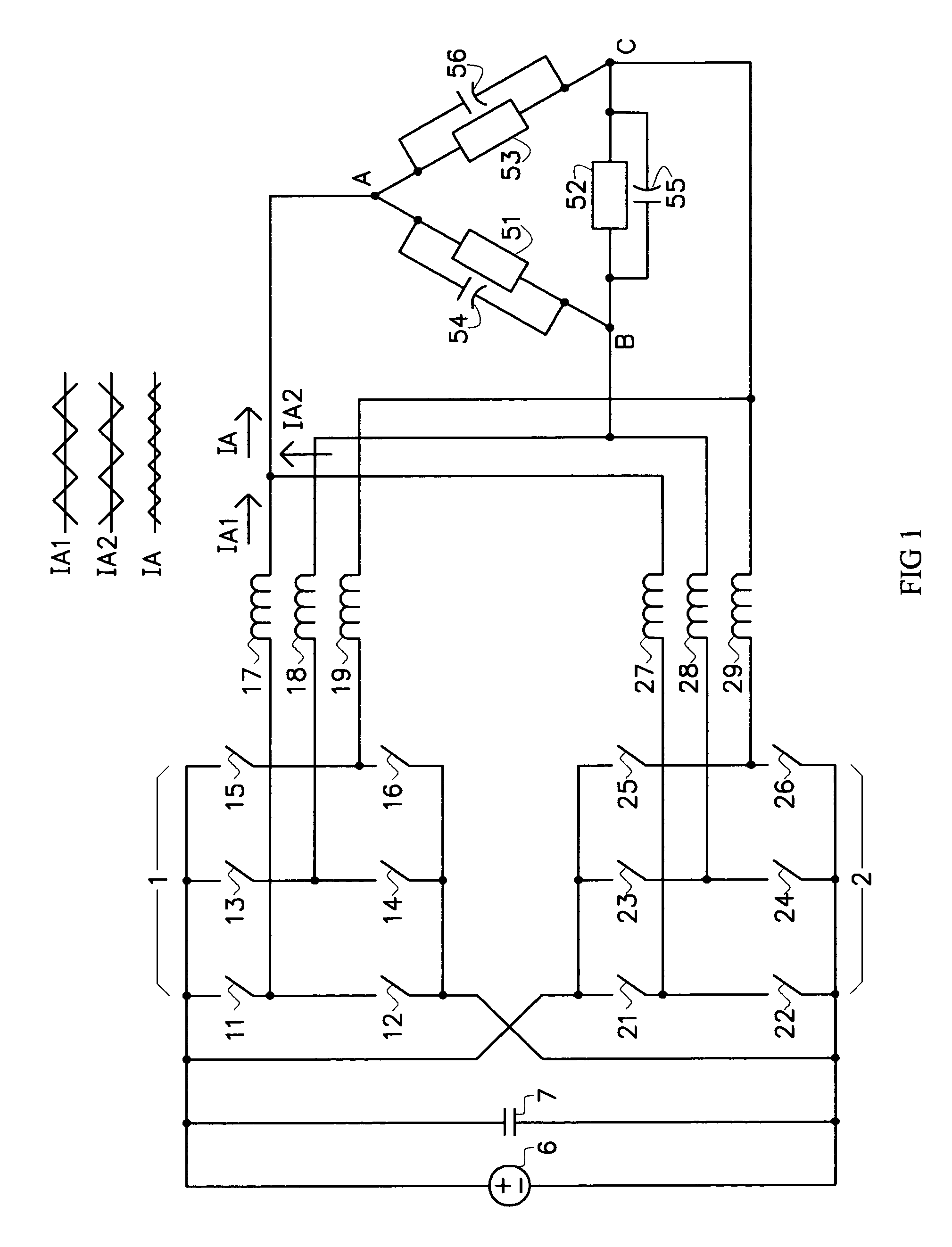
[0008]The following discussion illustrates the preferred embodiment of the invention. FIG. 1 shows two typical, three-phase bridge circuits, 1 and 2, connected to a common DC source, 6. The high frequency switching elements 11–16 and 21–26 are typically Insulated Gate Bipolar Transistors (IGBTs) with anti-parallel diodes. Bridges 1 and 2 are operated to convert DC power to three-phase AC current delivered to AC utility lines A, B and C. Inductors 17–19 and 27–29 filter the PWM switching waveforms from the two bridges. Capacitors 54–56 provide a second filter pole and operate in conjunction with filter inductors 17–19 and 27–29. The common points A, B and C of capacitors 54–56 are the summing nodes for the individual inductor currents. 51, 52 and 53, for this discussion, are the “primary” windings of a distribution transformer where the “secondary” is connected to the utility grid.

[0009]In this application, a prior art control circuit commands switches 11–16 and 21–26 in each bridge ...


PUM


Abstract

The invention is an electrical power converter using multiple, high frequency switching elements where the individual switching elements are operated in a synchronous, time-skewed arrangement to provide optimum ripple current cancellation.

Description

BACKGROUND OF THE INVENTION[0001]Inverters for high power Distributed Energy (DE) systems currently use technology that is basically borrowed from the industrial motor drive, motive power and Uninterruptible Power Supply (UPS) industries. This adapted technology falls short of meeting critical requirements for commercially viable distributed energy systems.[0002]Prior art DE inverters utilize power magnetic components that are physically large and heavy to allow the inverter to work at high conversion efficiencies. Basically, the larger the magnetic components, the lower the semiconductor switching frequency, the lower the semiconductor switching losses, the higher the conversion efficiency. The finished size, weight and cost of the inverter are largely driven by the magnetic filter components. The inverter conversion efficiency, however, is not a performance parameter that can be traded off for smaller magnetic components because the cost of the “green” energy, from a photovoltaic ...

Claims


Application Information

Patent Timeline
Patent Type & Authority Patents(United States)
IPC IPC(8): H02M1/12H02M7/5387H02M7/5395
CPCH02M7/53875H02M1/12H02M7/5395H02M1/0043
Inventor WEST, RICHARD T.
Owner SCHNEIDER ELECTRIC SOLAR INVERTERS USA
Why Eureka
Try Eureka