Transformerless static voltage inverter for battery systems

a transformerless static voltage and battery technology, which is applied in the direction of power conversion systems, electrical apparatus, dc source parallel operation, etc., can solve the problems of transformer and/or inductors commonly used in transformers to dissipate power, output current becomes null, and the inverter loses power, so as to achieve weight reduction and enhance efficiency

Inactive Publication Date: 2006-05-16
SQUIRREL HLDG
View PDF8 Cites 254 Cited by
  • Summary
  • Abstract
  • Description
  • Claims
  • Application Information

AI Technical Summary

Benefits of technology

[0034]It has now been found and is the object of the present invention a new method and a relative inverter that substantially does not require any inductor (or transformer) and turn-off capacitor and has an enhanced efficiency compared to known inverters. Moreover the inverter of this invention has a markedly reduced weight and is outstandingl

Problems solved by technology

On the other hand, photovoltaic panels output an electric current when they are irradiated by a light source that may drive an electric load, however if a counter voltage exceeding a certain value is applied on the photovoltaic panel the output current becomes null.
Similarly, the available power becomes small also when the output voltage becomes very small.
The transformer and/or the inductors commonly us

Method used


Image

  • Transformerless static voltage inverter for battery systems
  • Transformerless static voltage inverter for battery systems
  • Transformerless static voltage inverter for battery systems

Examples


Embodiment Construction

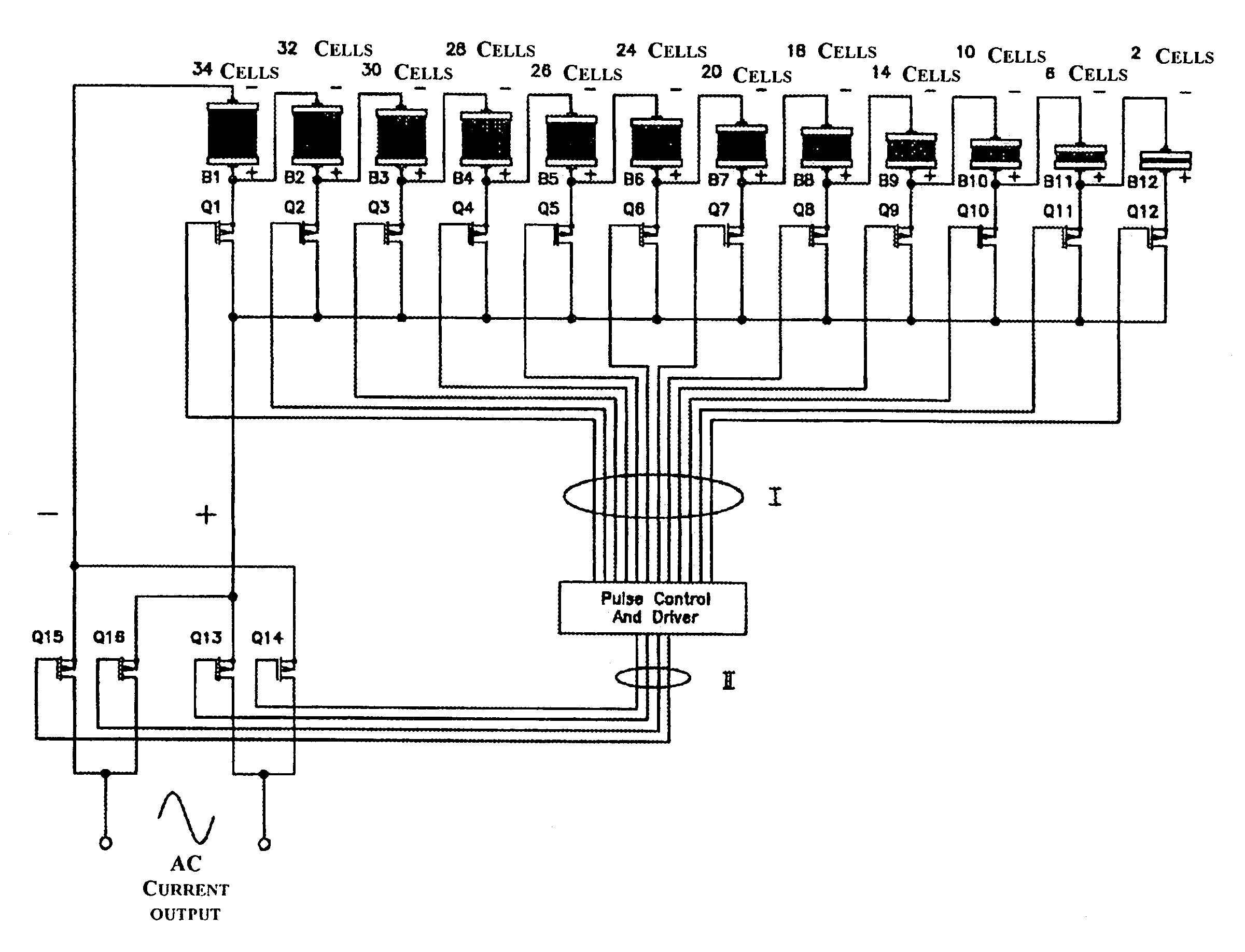
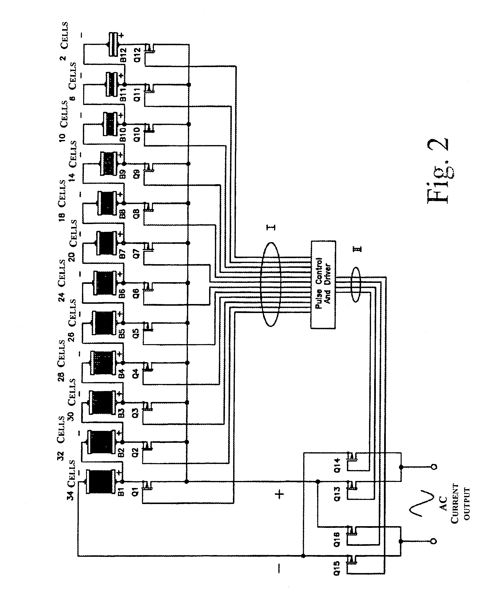
[0058]Referring to FIG. 2, the different intermediate voltage taps of the chain of elementary cells in series are established by employing twelve (N=12) batteries, B1, B2, . . . B11, B12, each composed of a pre-determined number of elementary cells such to be proportionate to, for the considered example, the value of the trigonometric sine function in the first quadrant.

[0059]In the depicted example, the first battery is constituted by 34 cells, the second battery by 32 cells, the third by 30 and so forth to the twelfth cell that is composed by only 2 elementary cells.

[0060]To each intermediate tap of such an electric series of DC current sources of a certain voltage, thus corresponding to a battery voltage that varies according to the trigonometric sine function in the first quadrant (of course the number of cells is proportional to the voltage at the terminals of the respective battery) is associated a power switch Q1, Q2, Q3 . . . Q11 and Q12, connecting each intermediate tap and...


PUM


Abstract

A static inverter for a battery of elementary, current sources or cells electrically in series and a number N of intermediate voltage taps along the chain of elementary DC current sources, wherein the number of elementary cells comprised between an intermediate tap and another intermediate tap adjacent to it or an end terminal of said chain is proportionate to the amplitude in the respective phase interval of a number N of discretization phases of the waveform of the AC voltage to be output in a quadrant; is implemented by arranging for: a number N of power switches each connecting a respective intermediate tap and a first end terminal of a first polarity of said chain of elementary cells in series to a common circuit node of said first polarity; an output bridge stage constituted by at least four power switches controlled in pairs for switching the current paths through the bridge stage, having a first pair of nodes coupled to said common circuit node of said first plurality and to the other end terminal of polarity opposite to said first polarity of said chain of elementary cells, respectively, and a second pair of nodes constituting an AC output; and a control circuit sequentially and cyclically turning on, in a continuous manner, one switch at the time of said N switches; each for a phase interval of 1/(4N) times the period of said AC output, and alternately tuning on by pairs said four power switches of said output bridge stage at every half a period.

Description

BACKGROUND OF THE INVENTION[0001]The present invention relates to systems for energy storage in batteries or for generating energy in fuel cells batteries employing static voltage inverters for converting electric energy stored or generated in batteries from DC to AC when powering electrical loads.[0002]Static voltage inverters for transforming DC electric power in an AC electric power at a certain voltage (for example 240 VAC) are commonly used in renewable power source plants, in “load-leveling” plants, in electric vehicles and the like, using storage batteries or primary batteries of fuel cells for generating energy to power AC loads.[0003]The possibility of converting the DC voltage of batteries of elementary cells, whether they are storage or secondary cells or primary cells such as fuel cells, to an AC voltage of voltage and frequency substantially similar to those of standard power distribution grids, is an important requisite for obvious compatibility reasons and often absol...

Claims


Application Information

Patent Timeline
IPC IPC(8): H02M7/00H02M7/48H02M7/487
CPCH02M7/483H02M7/00
Inventor ZOCCHI, ANDREASPAZIANTE, PLACIDO M.KAMPANATSANYAKORN, KRISADA
Owner SQUIRREL HLDG
Why Eureka
Try Eureka