Apparatuses, systems and methods for extravasation detection

Inactive Publication Date: 2006-05-16
BAYER HEALTHCARE LLC
View PDF57 Cites 78 Cited by
  • Summary
  • Abstract
  • Description
  • Claims
  • Application Information

AI Technical Summary

Benefits of technology

[0014]Current automated methods for detecting extravasation do not take adequate advantage of the inherent or designed properties of the injection fluid. In the case of a contrast medium, for example, the contrast medium is designed to affect a certain type or types of applied energy

Problems solved by technology

Current automated methods for detecting extravasation do not take adequat

Method used


Image

  • Apparatuses, systems and methods for extravasation detection
  • Apparatuses, systems and methods for extravasation detection
  • Apparatuses, systems and methods for extravasation detection

Examples


Embodiment Construction

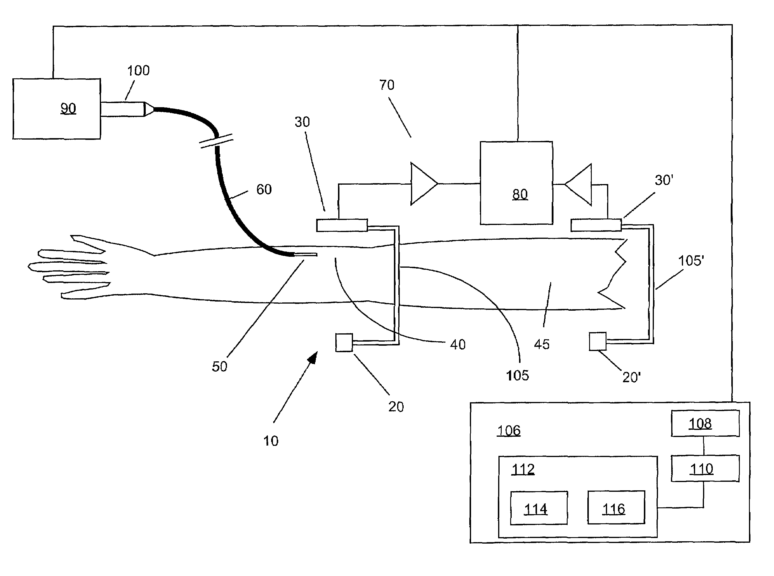
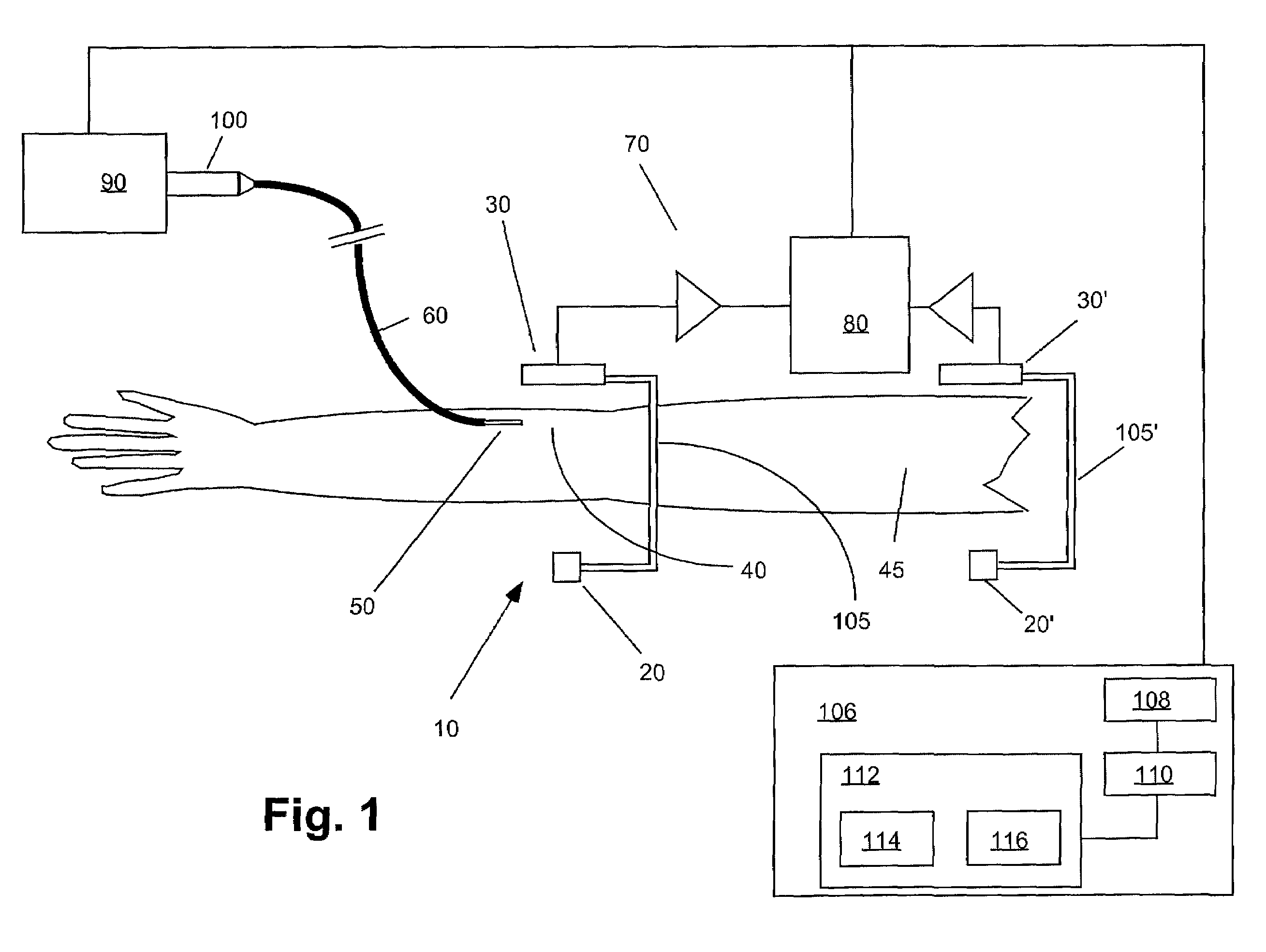
[0033]FIG. 1 illustrates one embodiment of an extravasation detection apparatus or device 10 of the present invention. Extravasation detection device 10 preferably includes an energy source 20 that is preferably positioned on one side of a site at which extravasation is to be detected. A sensor 30 suitable to detect a signal resulting from transmission of the energy emitted by energy source 20 may be positioned opposite energy source 20 such that energy (for example, X-ray energy or gamma ray energy) that is emitted by energy source 20 and is transmitted through the tissue of a patient's limb 45 is detected by sensor 30.

[0034]In the case that reflected energy is to be measured (for example, in the case of ultrasound energy), energy source 20 and sensor 30 are preferably positioned on the same side of a site. In FIG. 1, energy source 20 and sensor 30 are positioned about an injection site 40 on a patient's limb 45 as defined by injection needle 50, which is connected to a source of i...


PUM


Abstract

An apparatus for the detection of extravasation in an imaging procedure includes at least a first source of energy to supply imaging energy to tissue in the vicinity of a site and at least a first sensor to measure a signal resulting from the energy supplied to the tissue by the first imaging energy source. In preferred embodiment, the energy may be one of X-ray, gamma ray or ultrasound energy.

Description

CROSS-REFERENCE TO RELATED APPLICATION[0001]This application claims priority to U.S. Provisional Application Ser. No. 60 / 266,710, filed on Feb. 6, 2001.BACKGROUND OF THE INVENTION[0002]The present invention relates generally to the detection of extravasation of fluids injected into a patient, and, more particularly, to extravasation detection apparatuses, systems and methods in medical injection procedures using energy transmission through tissue in the vicinity of an injection site or other site.[0003]In many medical diagnostic and therapeutic procedures, a physician or other person injects a patient with a fluid. In recent years, a number of injector-actuated syringes and powered injectors for pressurized injection of contrast medium in procedures such as angiography, computed tomography, ultrasound and NMR / MRI have been developed.[0004]Extravasation is the accidental infusion of an injection fluid such as a contrast medium into tissue surrounding a blood vessel rather than into t...

Claims


Application Information

Patent Timeline
IPC IPC(8): A61B6/00
CPCA61M5/16836A61M5/007A61M2205/3375A61M2205/3313A61B5/03A61B5/0507A61B5/4878A61B2562/04G01N22/00Y10S128/13
Inventor DVORSKY, JAMES E.BOUTON, CHAD E.HIRSCHMAN, ALAN D.
Owner BAYER HEALTHCARE LLC
Why Eureka
Try Eureka