
Catalyst deterioration detecting apparatus

a detection apparatus and catalyst technology, applied in the direction of chemical analysis using combustion, machines/engines, process and machine control, etc., can solve the problems of insufficient reliability of hc sensor, inability to directly apply the judging method of deteriorated catalysts to diesel engines, and high cost of hc sensor, so as to accurately detect the deteriorated condition of catalysts

Active Publication Date: 2006-05-23
DENSO CORP
View PDF19 Cites 32 Cited by
  • Summary
  • Abstract
  • Description
  • Claims
  • Application Information

AI Technical Summary

Benefits of technology

[0013]In view of the above-described problems of conventional techniques, the present invention has an object to provide a catalyst deterioration detecting apparatus which is capable of accurately detecting the deteriorated condition of a catalyst by estimating a heat generation amount of combustible substances in a catalyst casing or by estimating a heat generation amount per unit flow amount of the combustible substances supplied to the catalyst.
[0014]Furthermore, the present invention has an object to provide a catalyst deterioration detecting apparatus which is capable of performing a highly accurate detection of catalyst deteriorated condition which is not adversely influenced by measuring error of the exhaust gas temperature.

Problems solved by technology

The catalyst deterioration judging method employed for gasoline engines cannot be directly applied to the diesel engines.
However, a reliable HC sensor has not been developed yet.
And also, the HC sensor will be expensive.
However, this judging method has not been practically used because the detection accuracy is not yet assured for every operating mode of an engine and also because the measuring accuracy of each exhaust gas temperature sensor is not yet reliable.
However, these conventional techniques are insufficient for solving the above-described deficiencies of Japanese patent No. 2593506.
The measuring error of each exhaust gas temperature sensor is negligible.
As understood from FIG. 11, it is difficult to accurately judge the deteriorated condition of a catalyst based on only the upstream / downstream exhaust gas temperature difference.
When a direct-type diesel engine is equipped with a DPF carrying a catalyst oxidizing the combustible substances (HC), it is difficult to directly measure the catalyst temperature in this DPF.

Method used


Image

  • Catalyst deterioration detecting apparatus
  • Catalyst deterioration detecting apparatus
  • Catalyst deterioration detecting apparatus

Examples


Embodiment Construction

[0041]A preferred embodiment of the present invention will be explained hereinafter with reference to attached drawings. Identical parts are denoted by the same reference numerals throughout the drawings.

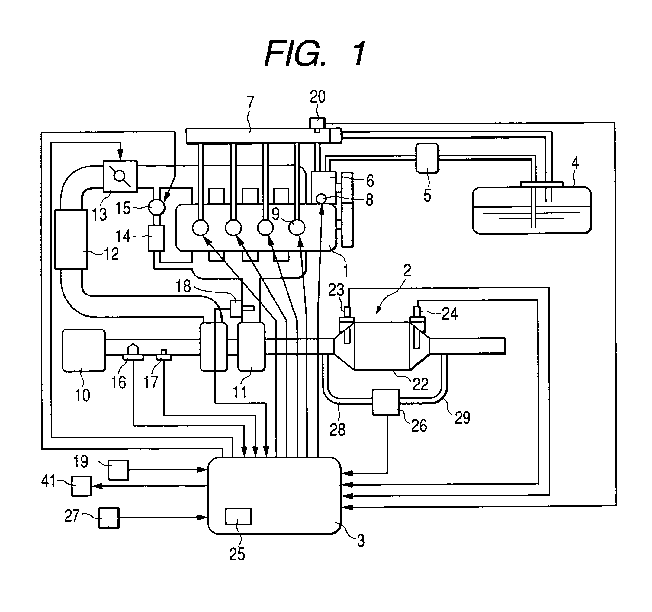
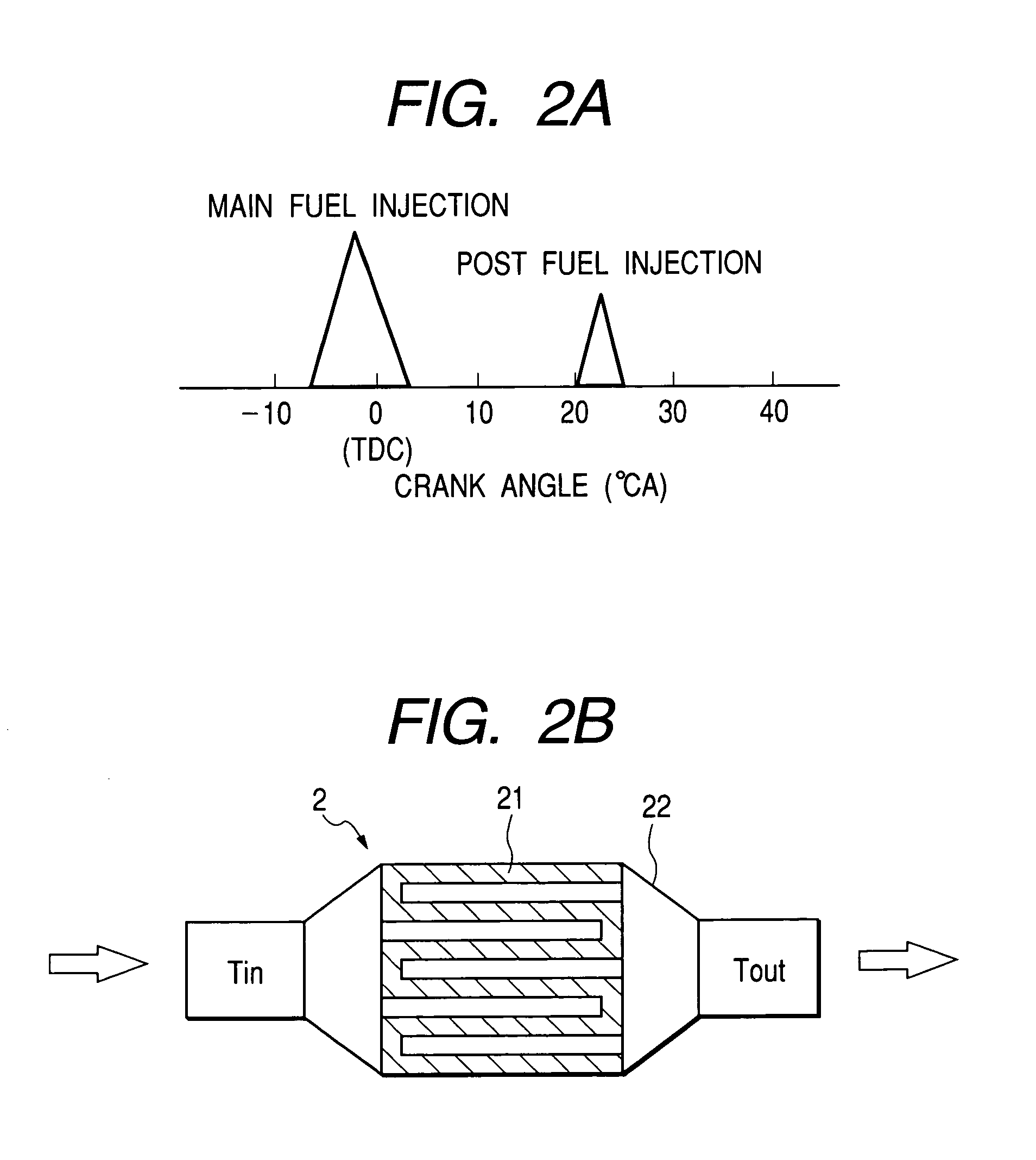
[0042]FIG. 1 shows an overall arrangement of a diesel engine control system. The diesel engine control system in according to this embodiment comprises a diesel engine 1 for an automotive vehicle. A common-rail type fuel injection apparatus is provided for injecting fuel into a combustion chamber of each cylinder of engine 1. A catalytic converter 2, serving as exhaust gas purification system for a diesel engine, is equipped in an exhaust gas passage of the engine 1. The catalytic converter 2 oxidizes harmful substances contained in the exhaust gas into harmless substances. For example, catalytic converter 2 converts carbon monoxide (CO) and hydrocarbon (HC) into carbon dioxide (CO2) and water vapor (H2O), respectively.

[0043]A catalyst deterioration detecting apparatus, associated w...


PUM


Abstract

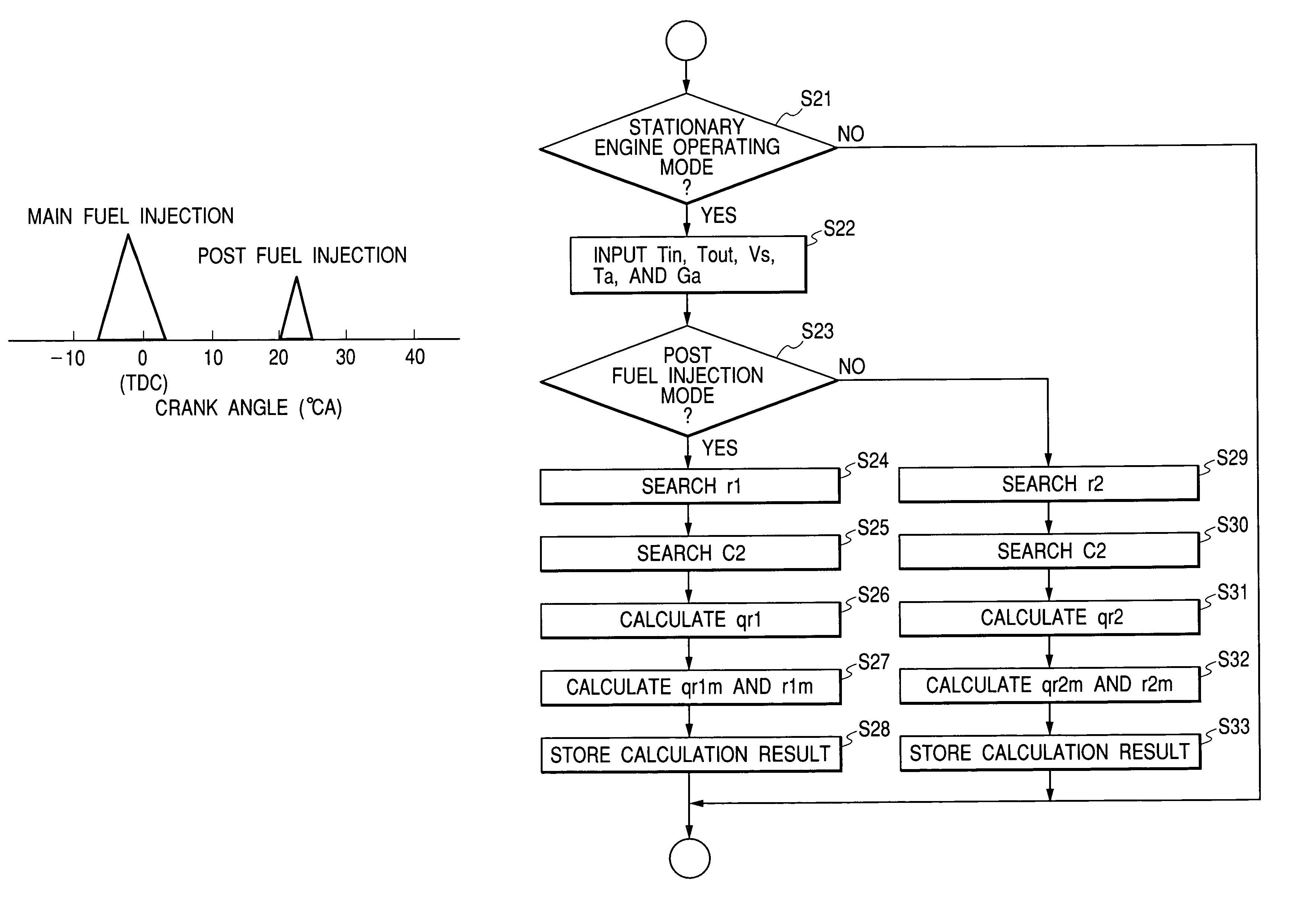
A heat generation amount qr / r per unit flow amount of combustible substances supplied to a catalyst is estimated based on upstream and downstream temperature information and supplemental engine information. A deteriorated condition of the catalyst is detected based on a judgement whether or not the estimated heat generation amount is smaller than a predetermined judging value D.

Description

BACKGROUND OF THE INVENTION[0001]The present invention relates to an exhaust gas purification system which purifies harmful substances contained in exhaust gas of an engine, and more particularly to a catalyst deterioration detecting apparatus for accurately detecting a deteriorated condition of a catalyst used for oxidizing combustible substances (e.g., HC) contained in the exhaust gas of a diesel engine. The present invention also relates to a catalyst deterioration alarming apparatus for alarming the deterioration of the catalyst.[0002]The gasoline engine is generally equipped with an oxygen concentration sensor to detect the oxygen concentration in the exhaust gas and to control an air-fuel ratio of gas mixture introduced into a combustion chamber of this engine. It is conventionally known that the oxygen concentration sensor can be used to detect deterioration of a ternary catalyst.[0003]Diesel engines are characterized in that the air-fuel ratio is set to a lean region compare...

Claims


Application Information

Patent Timeline
IPC IPC(8): G01N31/12F01N3/18G05D23/00G01N31/10G01N25/28F01N3/02F01N3/035F01N3/10F01N3/20F01N9/00F01N11/00F02B37/00F02D41/38F02D45/00G01N25/30
CPCF01N3/103F01N11/002G01N25/30F01N3/035F01N9/002F01N2430/085Y10T436/208339F02B37/00Y02T10/47Y02T10/22F01N2550/02Y02T10/12Y02T10/40Y02A50/20
Inventor KINUGAWA, MASUMISEKIGUCHI, KIYONORIKUBOSHIMA, TSUKASA
Owner DENSO CORP
Learn More