Electroluminescent lamp membrane switch

a technology of electroluminescent lamps and membrane switches, which is applied in the direction of legends, multi-contacts formed in one plate/layer, electrical apparatus, etc., can solve the problems of reduced cycle time and low marginal cost of providing these display elements, and achieves reduced cost and process time to produce, reduces the overall thickness of the membrane switch, and reduces the cost and process time

Active Publication Date: 2006-05-23
2461729 ONTARIO
View PDF73 Cites 21 Cited by
  • Summary
  • Abstract
  • Description
  • Claims
  • Application Information

AI Technical Summary

Benefits of technology

[0017]In accordance with the present invention, a depressable substrate is coated with a graphical layer and in a continuous process further coated with an electroluminescent lamp having a polyurethane insulation layer formed on the graphic layer. This structure provides the benefit of the graphic layer and the electroluminescent lamp being protected behind the substrate. The polyurethane insulating layer also protects the sensitive electroluminescent layers from contamination from the graphical inks.
[0018]Graphical layers and electroluminescent lamp lighting may also be advantageously combined to form display elements. These display elem

Problems solved by technology

There is a reduction in cycle time due to the elimination of the die cutting and expensive labor intensive lamination steps.
The marginal cost of provi

Method used


Image

  • Electroluminescent lamp membrane switch
  • Electroluminescent lamp membrane switch
  • Electroluminescent lamp membrane switch

Examples


Embodiment Construction

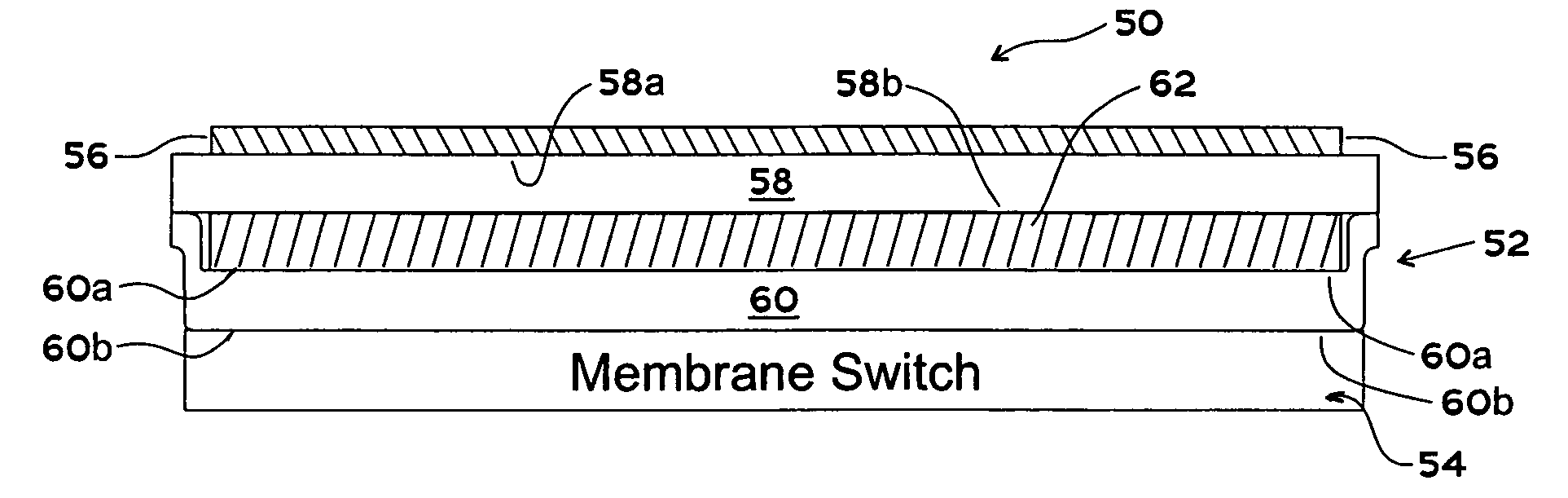
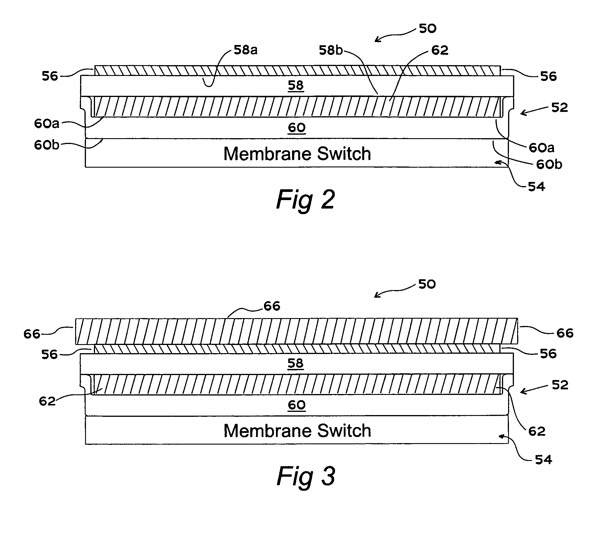
[0035]Referring to FIG. 2, the present continuously printed electroluminescent lamp membrane switch combination is illustrated, and is generally identified by the numeral 50. Switch 50 includes an electroluminescent lamp membrane system, generally identified by the numeral 52, a membrane switch, generally identified by the numeral 54 and a graphics layer 56. Lamp system 52 includes a top insulating layer 58 and a bottom insulating layer 60. Top layer 58 has a front surface 58a and a back surface 58b. Bottom insulating layer 60 includes a front surface 60a and a back surface 60b. Disposed between insulating layers 58 and 60 is an electroluminescent lamp 62. Lamp 62 includes various layers which will subsequently be described with respect to FIG. 8. Lamp 62 may comprise, for example, the electroluminescent lamp shown and described in U.S. Pat. No. 5,856,030, which disclosure and drawings are hereby incorporated by reference.

[0036]Top insulating layer 58 of lamp system 52 is directly i...


PUM


Abstract

An electroluminescent lamp membrane switch includes a deformable substrate. Graphic indicia is imprinted on the substrate. An electroluminescent lamp is imprinted on the graphic indicia layer and a membrane switch is formed on the lamp.

Description

TECHNICAL FIELD OF THE INVENTION[0001]The present invention relates to membrane switches, and more particularly to an integrated electroluminescent lamp system and membrane switch which reduces labor costs and cycle time in membrane switch manufacturing.BACKGROUND OF THE INVENTION[0002]Conventional membrane switches are typically manufactured individually by laminating several independent elements with interposed double-sided adhesive sheets. The steps of die cutting, lamination, and assembly are repeated multiple times during manufacturing leading to a labor intensive and slow process. The typical elements of a membrane switch include a graphic layer, laminating adhesive, embossed electrical contactors, spacer, electrical contact, laminate adhesive, and backing. These elements are individually manufactured, individually die cut and assembled layer by layer. Additionally, in many cases additional steps are required when adding an electroluminescent lamp and / or LED to backlight the s...

Claims


Application Information

Patent Timeline
IPC IPC(8): H01H9/16
CPCH01H13/83H01H9/182H01H2009/186H01H2205/032H01H2219/052H01H2219/02H01H2219/028H01H2219/046H01H2215/008
Inventor MARCUS, M. RICHARDBROWN, THOMAS L.
Owner 2461729 ONTARIO
Why Eureka
Try Eureka