Beamsplitter for high-power radiation

a beam splitter and radiation technology, applied in the direction of polarising elements, instruments, manufacturing tools, etc., can solve the problems of substantially undistorted window flat surfaces, and achieve the effects of excellent thermal conductivity of diamond, excellent thermal conduction on the substrate, and low wavefront distortion of the reflected (first) radiation beam

Inactive Publication Date: 2006-05-23
ULTRATECH INT INC
View PDF12 Cites 13 Cited by
  • Summary
  • Abstract
  • Description
  • Claims
  • Application Information

AI Technical Summary

Benefits of technology

[0013]A second aspect of the invention is a method of separating first and second polarization components from a polarized high-power polarized radiation beam. The method includes directing the high-power radiation beam to a polarizing beamsplitter having a thermally conducting frame and a window held in thermal contact within the frame. The window has a coating formed on a surface of a diamond substrate. The method also includes reflecting a portion of the high-power radiation beam from the window to form a first polarized radiation beam having the first polarization component, and transmitting through the window a portion of the high-power radiation beam to form a second radiation beam. The window absorbs a portion of high-power polarized radiation beam as heat. The method further includes removing the heat from the window by transmitting the heat to the frame and cooling the frame so that the temperature of the window remains near that of the coolant. The flat surfaces of the window remain substantially undistorted as a result of the excellent thermal conductivity of diamond. This keeps the wavefront distortion on the reflected (first) radiation beam low. Also, as a result of the excellent thermal conduction on the substrate and the low coefficient of index change with temperature for diamond, both the center-to-edge thermal and refractive index gradients are kept small. This keeps the wavefront distortion of the transmitted (second) radiation beam low.
[0014]A third aspect of the invention includes further processing the first or second polarized radiation beams with a second beamsplitter similar, or identical, to the first beamsplitter to increase the purity of the polarization in the first or second polarized radiation beam.

Problems solved by technology

The flat surfaces of the window remain substantially undistorted as a result of the excellent thermal conductivity of diamond.

Method used


Image

  • Beamsplitter for high-power radiation
  • Beamsplitter for high-power radiation
  • Beamsplitter for high-power radiation

Examples


Embodiment Construction

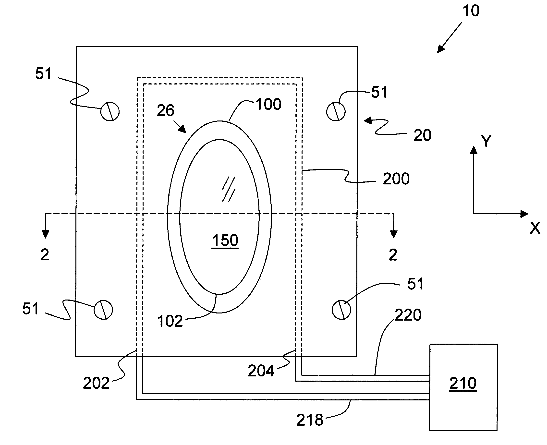
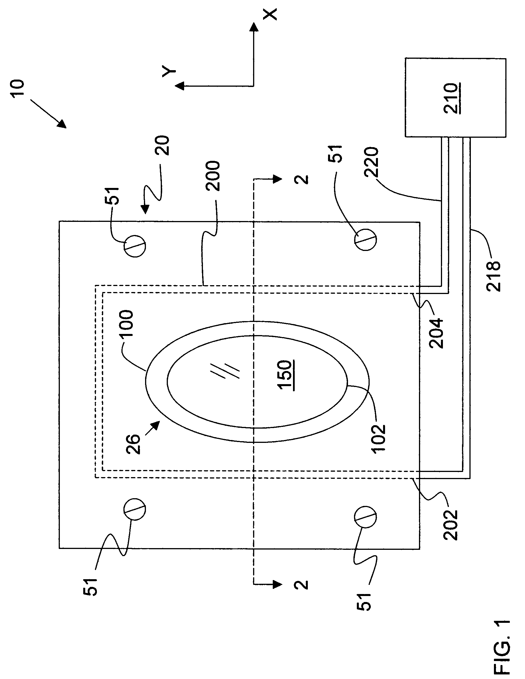
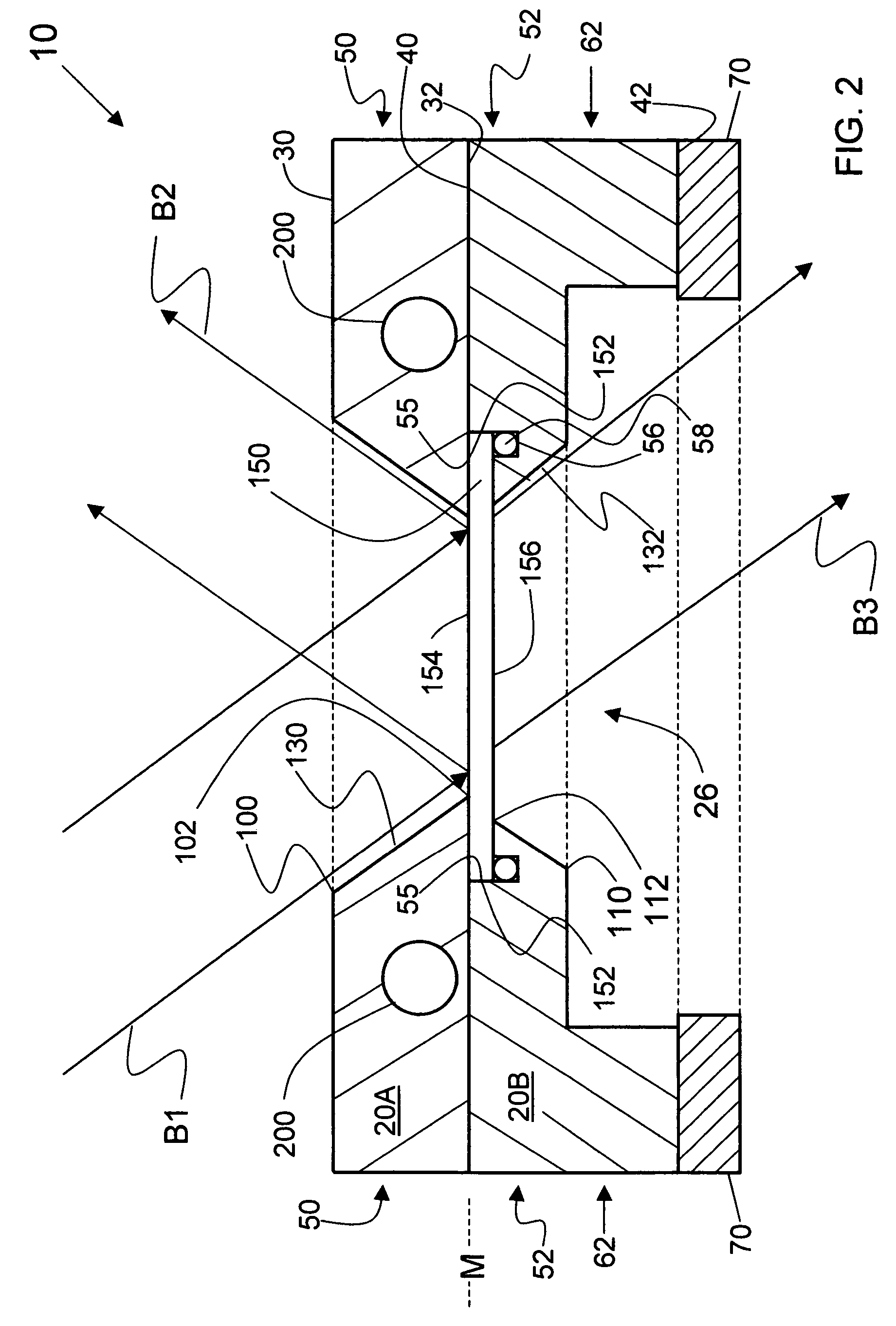
[0026]The present invention is directed to a component for splitting apart a high-power radiation beam, and / or combining two or more high power radiation beams, without introducing appreciable wavefront distortion. The same apparatus used for splitting one radiation beam into two beams can also be used to combine two beams into one beam. Thus, the term “beamsplitter” is used herein to describe the apparatus (component) of the present invention that can perform either of these operations (i.e., beamsplitting and beam combining).

[0027]In an example embodiment of the present invention, the beamsplitter of the present invention is non-polarizing, i.e., it can receive a single radiation beam and split it into two differently radiation beams, and vice versa. In another example embodiment, the beamsplitter is polarizing, i.e., it can receive a polarized radiation beam and split it into two polarized radiation beams, and vice versa.

[0028]FIG. 1 is a top-down view of an example embodiment of...


PUM

PropertyMeasurementUnit
poweraaaaaaaaaa
oblique angleaaaaaaaaaa
poweraaaaaaaaaa

Abstract

A beamsplitter apparatus for use with high-power radiation is disclosed. The apparatus includes a thermally conductive frame with a central aperture. The frame holds a window in the central aperture at the window's periphery. The window includes a diamond substrate with an optional coating formed thereon. Because the substrate is diamond and the frame is thermally conductive, the window is less susceptible to thermal effects caused by absorption of the incident radiation by the window. Thus, the original flatness of the widow surfaces is preserved, and variations in its index of refraction will be minimal. The result is that high-power radiation beams reflected from and transmitted by the widow remain substantially undistorted.

Description

CROSS REFERENCE[0001]This application is related to U.S. patent application Ser. No. 10 / 287,864 filed Nov. 4, 2002, with that application and the current application being co-owner by the same party.BACKGROUND OF THE INVENTION[0002]1. Field of the Invention[0003]The present invention relates to components used for splitting and / or combining radiation beams, and in particular to such components suitable for use with high-power radiation beams.[0004]2. Description of the Prior Art[0005]In certain industrial and manufacturing applications involving high-power radiation (e.g., radiation having a power of about 100 W or greater), it is important to maintain beam uniformity or otherwise preserve the integrity of the radiation beam wavefront. For example, in laser thermal annealing or LTA (also referred to as “laser thermal processing” or LTP), high-power laser radiation (e.g., 10.6 μm radiation from a CO2 laser) is used to quickly raise the surface temperature of a workpiece (e.g., substr...

Claims


Application Information

Patent Timeline
Patent Type & Authority Patents(United States)
IPC IPC(8): B23K26/06G02B5/30B23K26/067G02B1/02G02B7/00G02B27/28
CPCB23K26/067G02B1/02G02B27/144G02B27/145G02B7/008B23K2201/42G02B27/283G02B27/14B23K2101/42B23K2103/56
Inventor LANDAU, IGOR
Owner ULTRATECH INT INC
Why Eureka
Try Eureka