
Combination battery, light bulb, and fuse tester

a technology for fuses and batteries, applied in the direction of fuses testing, material impedance, instruments, etc., can solve the problems of difficult to determine the condition of bulbs or fuse merely by looking, particularly distressing, etc., and achieve the effect of accurate results, convenient use and inexpensive production

Inactive Publication Date: 2006-05-23
HSN IMPROVEMENTS
View PDF24 Cites 36 Cited by
  • Summary
  • Abstract
  • Description
  • Claims
  • Application Information

AI Technical Summary

Benefits of technology

[0012]The present invention provides an improved combination battery, light bulb, and fuse tester. In particular, the present invention provides a novel battery, light bulb, and fuse tester which is easy to use, especially for elderly individuals, which provides accurate results, and which is inexpensive to produce. According to the invention, the battery tester includes a novel battery testing probe mechanism. Preferably, such a probe mechanism may be comprised of two pincer-like probe arms which may be easily manipulated to clamp a battery, fuse or light bulb to be tested between electrical contacts located therein. More preferably, the probe arms may include a resiliently biased gearing mechanism in order to easily move the probe arms towards and away from one another. The probe arms may be controlled by an actuator, the actuator preferably being a resiliently biased trigger operatively connected thereto.
[0014]In a preferred embodiment, a series of transistors may be integrated into the circuit to turn on appropriate LEDs to indicate the condition of the battery. For example, RED, AMBER or GREEN LEDs may be used to indicate “bad”, “low”, “good” battery conditions depending on what the battery terminal voltage is for a given battery type being tested. In order to produce a highly sensitive tester, a set of potentiometers may be built into the integrated circuit for trimming each tester circuit to the desired cutoff voltage. In such a set-up, a single potentiometer may be used for each LED circuit thereby allowing the load resistance to be set within a range that is closer and more accurate than any range that would be possible without the use of trimmable potentiometers. In this preferred embodiment, the circuits may be tuned or “trimmed” at the factory using sensitive test equipment to desired threshold voltages, and then locked in place using a dab of paint or adhesive. In this way, a high degree of accuracy and repeatability may be calibrated into a preferred embodiment of a battery tester in accordance with the present invention.
[0018]In a further preferred embodiment, the tester of the present invention may include a feature for facilitating the contacting of the battery poles to the electrical contacts on the probe ends. In particular, given that batteries generally have cases made of one type of steel or another, the use of a magnetic electrical contact for one of the probes can facilitate the testing of batteries, especially for those without particularly nimble fingers. This magnetic electrical contact feature makes the invention especially easy to use over prior art battery testers in that the user does not need to carefully place a small battery into a slot, receptacle, or otherwise exhibit excellent eye-hand coordination in order to use the tester. Furthermore, there is little possibility of the battery falling out of the tester once the battery is placed against the magnetic tip.

Problems solved by technology

Furthermore, it is noted that some of the batteries that need to be tested, such as the small “button” cells which are increasingly being used for powering more and more electronic devices, can pose particular problems, given their small size, for the elderly to manipulate.
This can be particularly distressing given that these batteries are of the type that are generally used in hearing aids.
Just as it is not possible to determine the condition of a battery by looking at it, it is likewise impossible (in many cases) to determine the condition of a bulb or fuse merely by looking at it.
Small bulbs, such as those used in Christmas light strings, are often colored and use small filaments, so it is not easy to know if the filament is broken or burned out by observation.
As another example, it is difficult to determine if a small Halogen “pin” bulb is burned out or not because the filaments inside these bulbs are typically difficult to observe through the relatively thick glass of the bulb.
In addition, some small automotive fuses are hard to “read” by observation.
When the filament burns out or is broken, then of course current cannot pass through the filament and therefore it will not produce light.
The fuse thus sacrifices itself to protect other more sensitive and expensive components in the circuit, including the circuit wiring.
Such accurate testing can generally not be accomplished using a simple open circuit-type terminal voltage tester, instead requiring a load-based tester.
And while such testers do not generally require the use of a complicated electronic circuit, integrated circuit (IC), or a microprocessor, thereby making them relatively inexpensive to design and make, the results obtained using such testers are not nearly as accurate or consistent as the results obtained using a load-based battery tester.
More specifically, open circuit-type testers are relatively limited in value because they do not test a battery under a realistic “load” condition.
However, as noted above, load testers, because they must apply a given load that is dependent on the properties of the battery being tested, normally require more sophisticated electronic circuits than open circuit testers.
At some point, called the cutoff voltage, the battery can no longer provide sufficient electrical energy to power an electronic device.

Method used


Image

  • Combination battery, light bulb, and fuse tester
  • Combination battery, light bulb, and fuse tester
  • Combination battery, light bulb, and fuse tester

Examples


Embodiment Construction

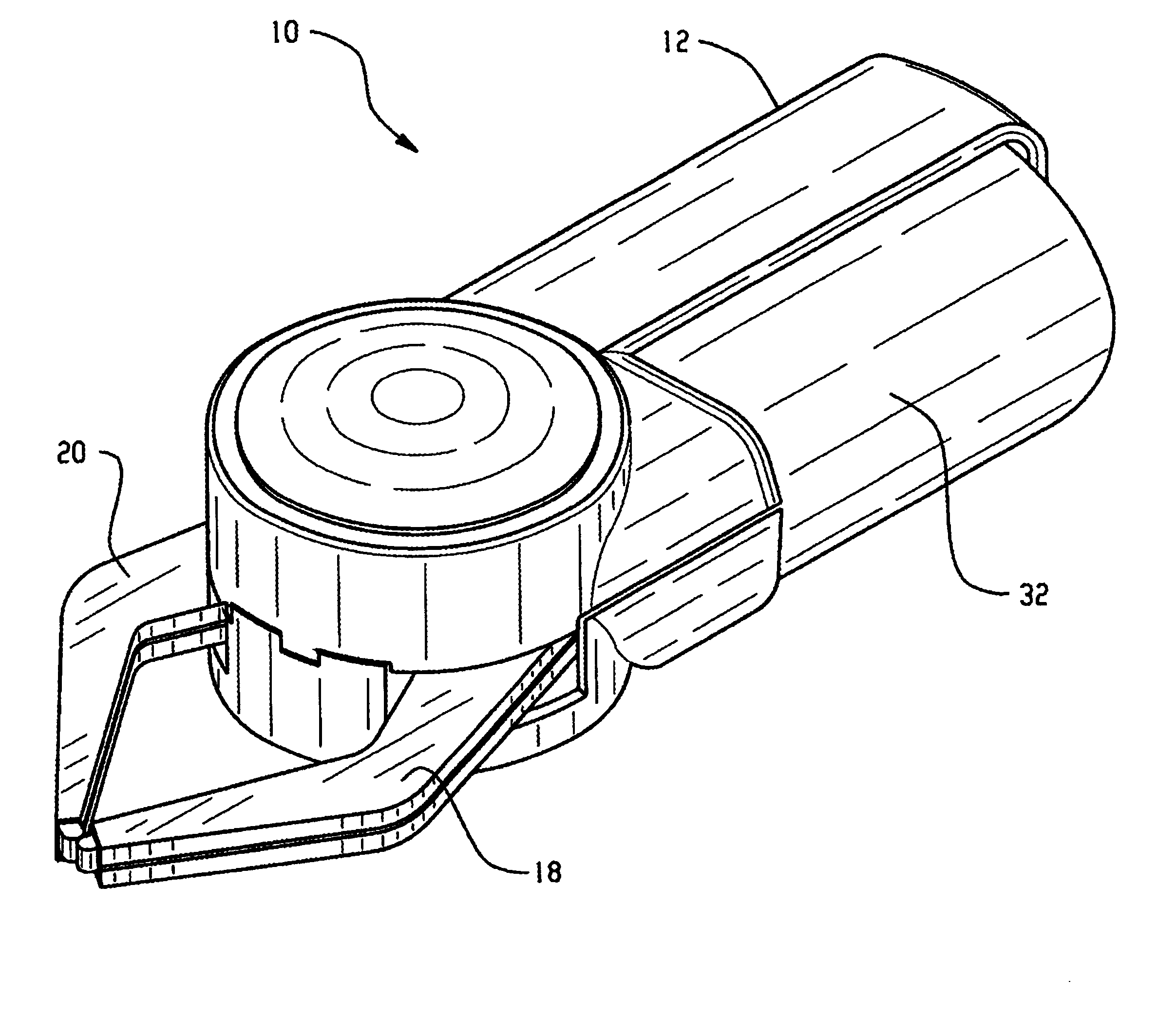
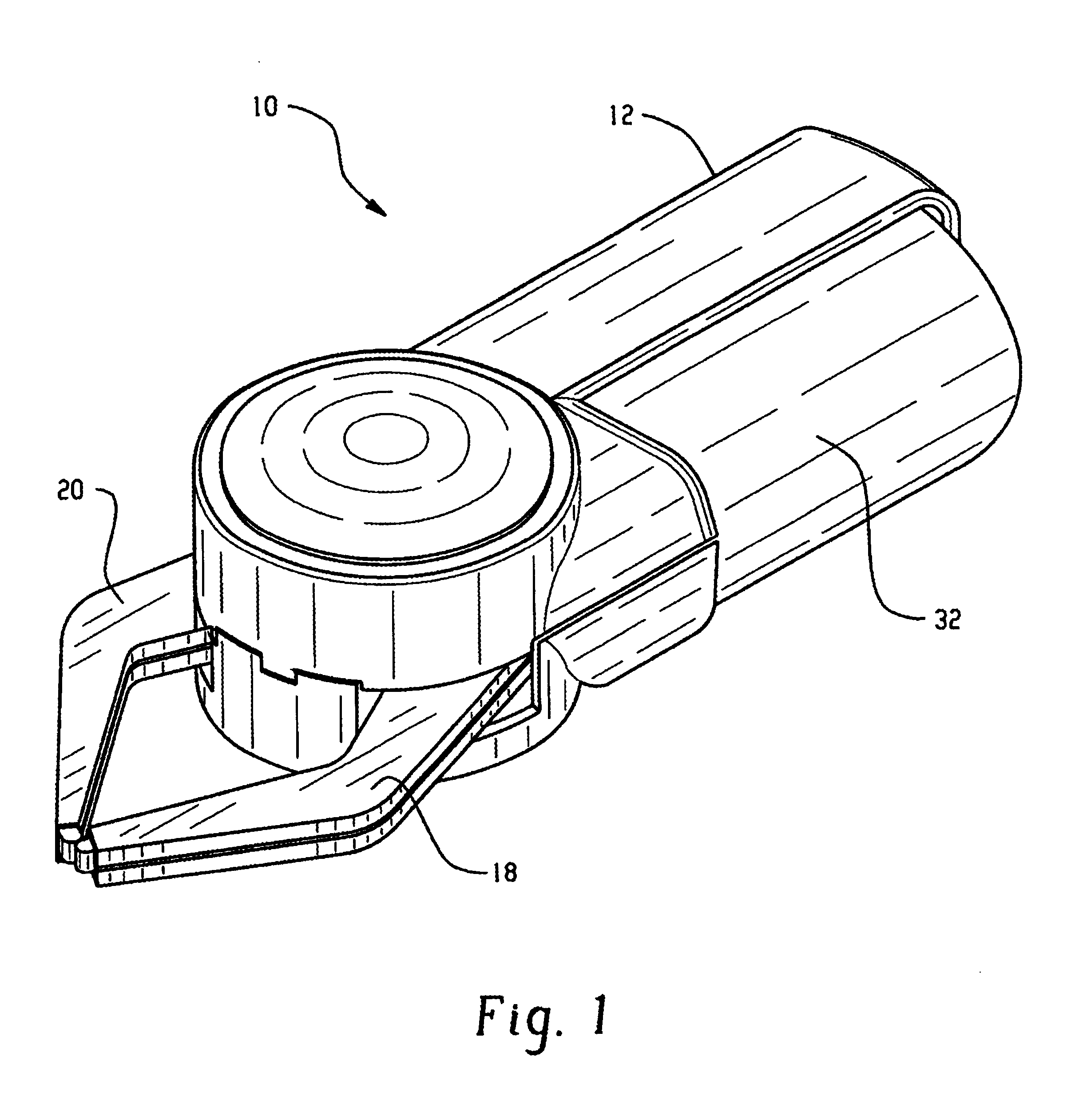
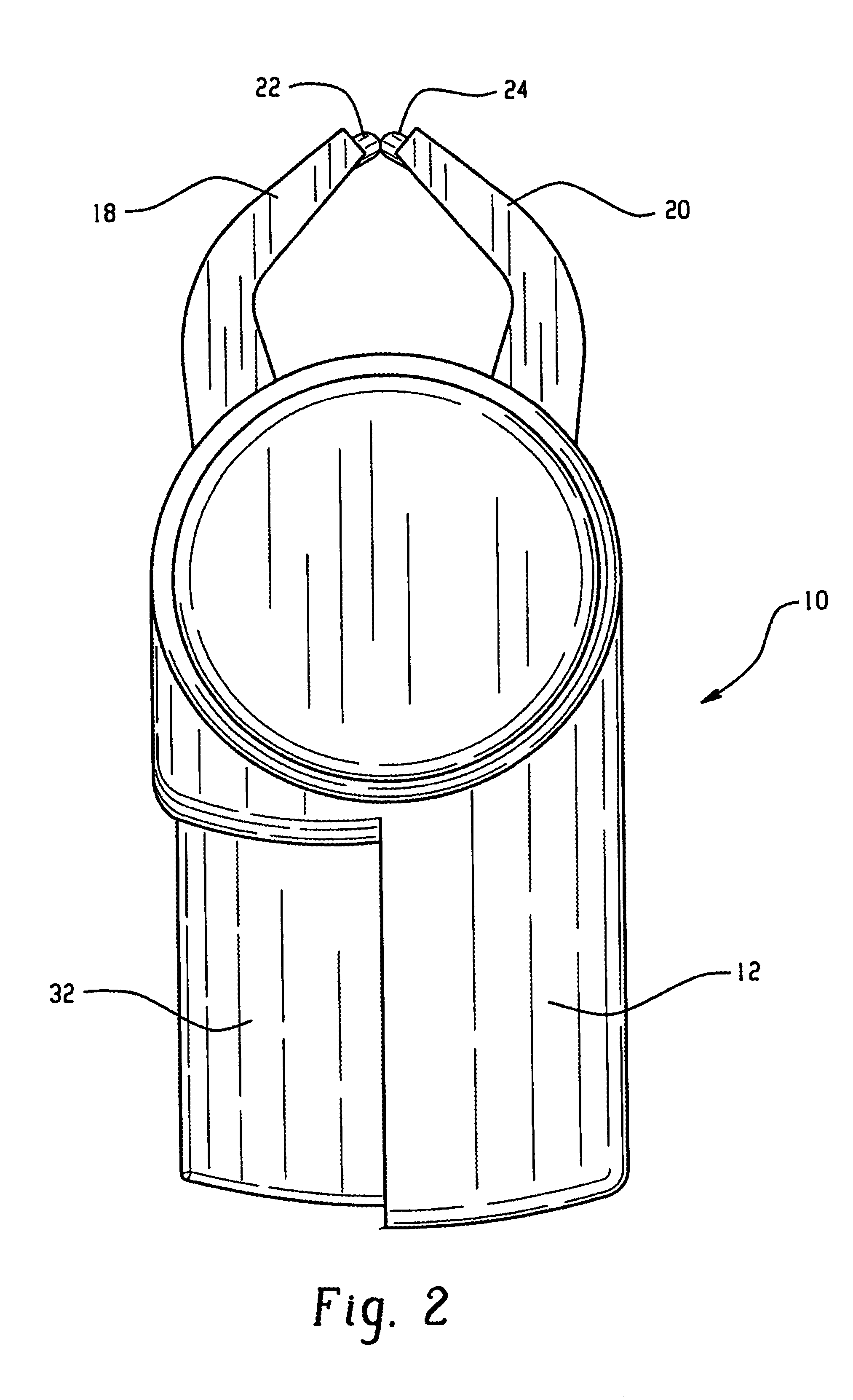
[0028]The present invention provides a combination battery, light bulb, fuse tester 10. In particular, the present invention provides a novel battery, light bulb, and fuse tester 10 which is easy to use, especially for elderly individuals, which provides accurate results, and which is inexpensive to produce. According to the invention, as best seen in FIG. 4, the battery tester 10 includes a case 12 housing a novel battery testing probe mechanism 14 comprised of two pincer-like probe arms 18,20 which may be easily manipulated to clamp a battery, fuse or light bulb (not shown) to be tested between electrical contacts 22, 24 located thereon.

[0029]Preferably, as best seen in FIGS. 5 and 6, the probe arms 18, 20 include a resiliently biased gearing mechanism 26 in order to easily move the probe arms 18, 20 towards and away from one another. The probe arms 18, 20 are controlled by an actuator 28, the actuator 28 preferably including a resiliently biased trigger 32 operatively connected t...


PUM


Abstract

A combination battery, light bulb, fuse tester having novel features. In particular, the tester includes a novel probe apparatus including an actuator, a pair of opposed probe arms, each of the probe arms having an electrical contact on an end thereof, the probe arms being adapted such that operation of the actuator biases the ends of the probe arms away from each other to an open position allowing the electrical poles of a battery, light bulb, or fuse to be tested to be contacted by the contacts on the probe arms. Additional features include magnetic probe contacts to facilitate the testing of a battery, light bulb, or fuse.

Description

BACKGROUND OF THE INVENTION[0001]The present invention relates to a device and method for testing batteries, light bulbs, and fuses. More specifically, the invention relates to a device and method for testing batteries, light bulbs and fuses which provides accurate, easy-to-read results as to the condition of the item being tested, which is relatively simple to use, and which is ergonomic in design and operation.[0002]In particular, this invention relates to battery testers as commonly used for testing dry cell batteries. The term battery may be used collectively in the present context to include reference to single as well as multiple cells. The widespread use of batteries in consumer appliances, such as portable AM / FM radios, CD players, MP3 players, watches, calculators, hearing aids, PDA's, toys, games, etc., has given rise to a significant demand for devices for testing them. Furthermore, it is noted that some of the batteries that need to be tested, such as the small “button” ...

Claims


Application Information

Patent Timeline
IPC IPC(8): G01N27/416G01R31/36G01R31/74
CPCG01R31/3627G01R31/07G01R31/385G01R31/74
Inventor KUNG, CHI HUNG
Owner HSN IMPROVEMENTS
Learn More