Open magnet device and magnetic resonance imaging apparatus comprising it

a magnetic resonance imaging and open magnet technology, applied in the field of magnetic devices, can solve the problems of generating eddy currents, affecting image quality, and unable to correct asymmetrical eddy currents, and achieve the effect of reducing eddy current asymmetry

Inactive Publication Date: 2006-05-23
HITACHI MEDICAL CORP
View PDF21 Cites 8 Cited by
  • Summary
  • Abstract
  • Description
  • Claims
  • Application Information

AI Technical Summary

Benefits of technology

[0013]According to this embodiment, generation of asymmetric eddy currents in the vacuum vessels and vacuum vessel coupling means can be prevented. Particularly in the case that the heat shield coupling means have continuous or intermittent slits, no current that would be a cause for generation of asymmetric eddy currents in the heat shields flows in the heat shield coupling means. The slit portion is preferably positioned at least on the center side of the heat shield coupling means in the anterior and posterior direction and in the transverse (right and left) direction (that is, on the measurement space side).
[0015]By symmetric positions is meant that the positions are symmetrical with respect to the center axis in the anterior and posterior direction and with respect to the center axis in the transverse (right and left) direction of the heat shields. Provision of the recesses in such positions, which are electrically equivalent to the holes, reduces asymmetry of eddy currents caused by presence of the holes.
[0016]According to the first and second embodiments of the present invention, the problem of asymmetric eddy currents can be solved not on the vacuum vessel side, which is required to meet a severer condition of high sealing, but on the heat shield side.
[0019]According to the third and fourth embodiments, the generation of asymmetric eddy currents in the vacuum vessels and the coupling means thereof is prevented. In this case too, the slit portion of the vacuum vessel coupling means is preferably provided at least on the center side in the anterior and posterior direction and in the transverse direction of the heat shields (that is, on the measurement space side).
[0024]According to the present invention, asymmetric eddy currents can be reduced without need for a special correcting coil or other means for correcting asymmetric eddy currents or means for reducing leakage of magnetic flux from the gradient magnetic field coil. Since generation of spatially asymmetric eddy currents in the magnet device can be thus prevented effectively, deterioration of images due to eddy currents can be minimized in the MRI apparatus employing the magnet device according to the present invention.

Problems solved by technology

Since such a heat shield plate is made of a material of good heat conductivity and low electric resistance, the problem of generation of eddy currents also arises in these plates as in the vacuum vessels.
The asymmetrical eddy currents cause artifacts in images produced by the MRI apparatus and degrades image quality.
Such asymmetrical eddy currents cannot be corrected by adjusting the current waveform of the magnetic field generating unit.

Method used


Image

  • Open magnet device and magnetic resonance imaging apparatus comprising it
  • Open magnet device and magnetic resonance imaging apparatus comprising it
  • Open magnet device and magnetic resonance imaging apparatus comprising it

Examples


first embodiment

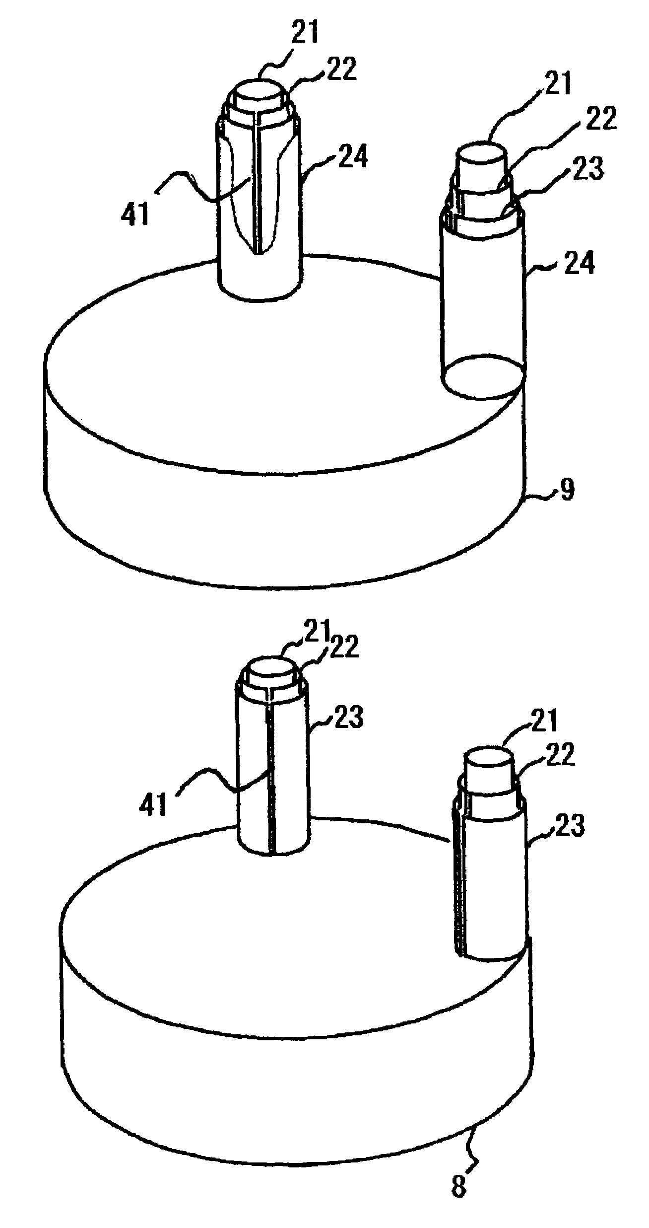
[0047]FIG. 4 is a perspective view of the lower portion of a vacuum vessel 9 of the first embodiment, and FIG. 5 is a perspective view of the lower portion of the interior of the vacuum vessel 9. In this embodiment, the vacuum vessels 9 and coupling conduits 24 are made of a high electric-resistance material such as stainless steel so that a magnetic flux of the gradient magnetic field coil reaches the second heat shields 8. In other words, eddy currents are deliberately generated in the second heat shields 8 and coupling conduits 23 so as to suppress generation of eddy currents in the vacuum vessels 9 and coupling conduits 24.

[0048]However, in a case of only making the vacuum vessels 9 and coupling conduit 24 of a high electric-resistance material, eddy currents are generated in the second heat shields 8 and coupling conduits 23 asymmetrically with respect to the X-axis in the figure due to pulse-like change of the magnetic fields generated by the gradient magnetic field coils as e...

third embodiment

[0059]Specifically, the present invention employs the coupling conduits 24 of the vacuum vessels 9 having slits similar to those shown in FIGS. 5 and 6 and lids that cover the slits and are electrically insulated from other parts, while it employs the vacuum vessels 9 and coupling conduits 24 made of a low electric-resistance material. Such a slit establishes a region where current does not flow. Alternatively, it is possible to cope with the asymmetrical eddy currents by making only the coupling conduits 24 (but not the vacuum vessels 9) of a high electric-resistance material.

[0060]In a fourth embodiment, holes having the same shape as those of the holes connecting the inner space of the coupling conduit 24 to the inner space of the vacuum vessels 9 are further provided symmetrically with respect to both of the X-axis and Y-axis in order to further reduce the asymmetry of eddy currents. Lids of a high electric-resistance material are also provided to keep the vacuum vessels 9 seale...


PUM

PropertyMeasurementUnit
temperatureaaaaaaaaaa
magnetic fieldaaaaaaaaaa

Abstract

In a superconductive magnet device comprising upper and lower vacuum vessels coupled by a coupling conduit, the upper and lower vacuum vessels 9 and the coupling conduit 24 coupling them are made of a high electric-resistance material so that the magnetic flux of gradient magnetic field coils reaches the upper and lower pair of a second heat shields 8 and a coupling conduit 23 coupling the pair of the second heat shields 8. The coupling conduit 23 coupling the upper and lower pair of the second heat shields 8 is provided with a slit (cut) 41 extending in the vertical direction so that no eddy currents occur and thus eddy currents generated asymmetrically in the coupling conduit 23 are reduced. Artifacts caused by asymmetrical eddy currents can by reduced in an MRI apparatus using such a magnet device.

Description

TECHNICAL FIELD[0001]The present invention relates to a magnet device used for a magnetic resonance imaging apparatus (hereinafter referred as “MRI apparatus”). In particular, it relates to a technique for suppressing eddy currents produced within the magnet device by gradient magnetic field coils of an MRI apparatus.RELATED ART[0002]A conventional MRI apparatus is equipped with a static magnetic field magnet for generating a static magnetic field, gradient magnetic field coils for generating gradient magnetic fields and an RF coil, and applies RF pulses produced by the RF coil to a subject under examination (e.g., a patient) placed in the static and gradient magnetic fields to excite atomic nuclear spins, and detects NMR signals emitted by the spins to produce tomograms of the subject.[0003]Such MRI apparatuses are often equipped with a superconductive magnet as the static magnetic field magnet. While a superconductive magnet is typically a solenoid type magnet that generates a mag...

Claims


Application Information

Patent Timeline
Patent Type & Authority Patents(United States)
IPC IPC(8): H01F3/00G01V3/00H01F6/00H01F7/00A61B5/055G01R33/38G01R33/3815G01R33/565
CPCG01R33/3806G01R33/3815G01R33/56518
Inventor YOSHINO, HITOSHIGOLDIE, FRED
Owner HITACHI MEDICAL CORP
Why Eureka
Try Eureka