
Photomask for near-field exposure and exposure apparatus including the photomask for making a pattern

a near-field exposure and pattern technology, applied in the field of near-field light exposure photomasks, can solve the problems of low throughput of lithographic apparatus including the near-field optical microscope, the inability to disclose or suggest the dependence of the light intensity right below the aperture on the thickness, and the inability to solve the problem of photolithography

Inactive Publication Date: 2006-05-23
CANON KK
View PDF5 Cites 18 Cited by
  • Summary
  • Abstract
  • Description
  • Claims
  • Application Information

AI Technical Summary

Benefits of technology

The present invention provides a photomask for near-field light exposure that ensures required light intensity right below the aperture of a shading member. The photomask includes a transparent substrate and a shading member with a mask pattern including an aperture with a width not greater than the wavelength of light from a light source. The shading member has a thickness that provides the required light intensity right below the aperture in consideration of the width of the aperture. The mask pattern includes at least two apertures having different widths, and the thickness of the shading member is determined such that the difference in light intensity right below the apertures is 20% or less. The thickness of the shading member is also determined such that the rate of change in light intensity to a minute variation of the width of the aperture is 2% / nm or less. The method and apparatus for making a pattern using the photomask are also provided.

Problems solved by technology

For achieving a higher resolution of less than 0.1 m, however, photolithography still has some unsolved problems, such as development of light sources that can emit shorter-wavelength light and development of lenses that can be used in this wavelength region.
The lithographic apparatus including the near-field optical microscope has the disadvantage of low throughput because micromachining is performed with one or several processing probes with a single stoke.
However, these known technologies do not disclose or suggest the dependence of the light intensity right below the aperture on the thickness of the shading film and the width of the aperture formed in the shading film, although they suggest some thickness information on the shading film of the photomask for near-field light exposure, as described above.
Thus, it is difficult to find a condition for exposing different positions through the apertures with the same light exposure.

Method used


Image

  • Photomask for near-field exposure and exposure apparatus including the photomask for making a pattern
  • Photomask for near-field exposure and exposure apparatus including the photomask for making a pattern
  • Photomask for near-field exposure and exposure apparatus including the photomask for making a pattern

Examples


first embodiment

[0035]In the first embodiment, the thickness of the shading member is controlled within an appropriate range to reduce a difference in light intensity right below apertures having different widths to 20% or less, resulting in uniform light exposure of a resist disposed right below the apertures. Thus, a resist pattern including lines having different widths can be readily exposed at one time. The difference in light intensity of 20% or less is a requirement for a practical process control that can suppress variations in patterning process conditions such as exposure time and developing time caused by the photomask. The difference in light intensity is preferably 10% or less, and more preferably 0%.

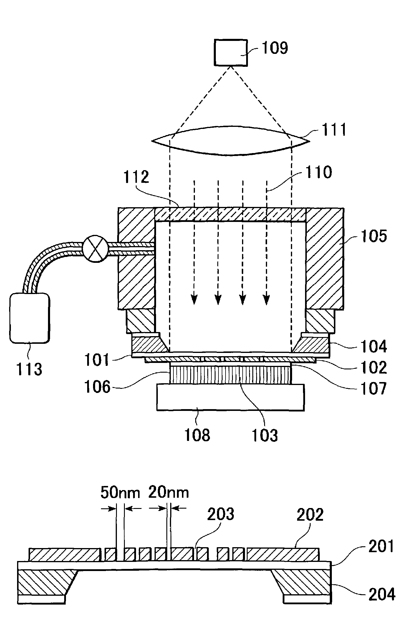
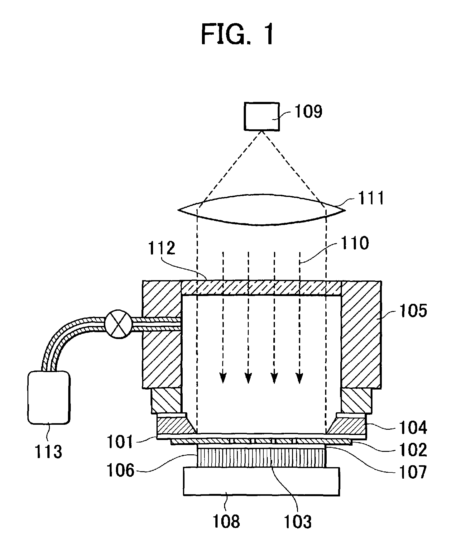
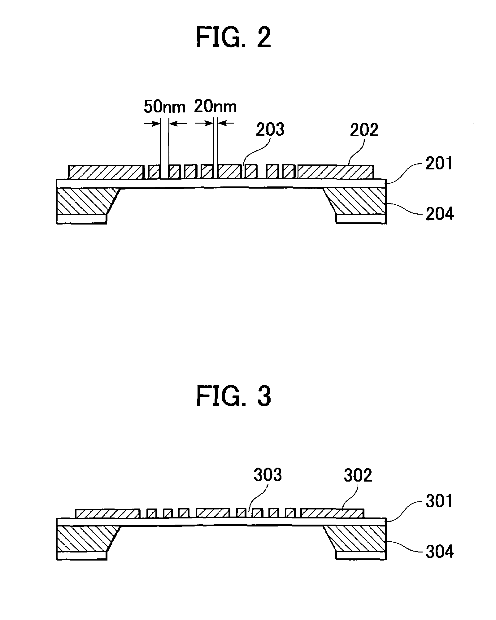
[0036]The first embodiment will now be described in further detail with reference to the drawings. FIG. 2 is a cross-sectional view of a photomask in accordance with the first embodiment, and FIG. 1 is a schematic cross-sectional view of an aligner having the photomask for evanescent light...

second embodiment

[0046]As described above, the fine aperture with reflectors at the two ends functions as a resonator in the photomask, and the wavelength of the propagation mode in the fine aperture depends on the width of the fine aperture. Thus, the transmitted light volume and the light intensity right below the aperture in the resonator is represented by a function of the ratio of the resonator length to the shading film thickness and the width of the fine aperture.

[0047]When the rate of change in the light intensity to the width of the aperture is controlled within the above range, the change in the light intensity right below the aperture can be suppressed. As a result, the change in size in the resist pattern can be suppressed. More specifically, the light intensity can be controlled within a variation of 2% or less when the aperture width varies by 1 nm. A change in light intensity is within 20% when the width of the fine aperture varies by 10 nm. The difference in light intensity of 20% or...

third embodiment

[0053]As described above, the fine aperture with reflectors at the two ends functions as a resonator in the photomask, and the wavelength of the propagation mode in the fine aperture depends on the width of the fine aperture. The length of the resonator corresponds to the thickness of the shading member. The light intensity right below the aperture is represented by a function of the thickness of the shading member and is a local maximum. With reference to the local maximum intensity, 0%-less to 50%-less light intensity may be used for exposure for achieving a large light volume right below the aperture and a sufficiently reduced light volume at the shading portion. Herein, “50%-less light intensity” represents 50% reduction in the light intensity, and is a requirement for a practical process control that can suppress variations in patterning process conditions such as exposure time and developing time caused by the photomask.

[0054]Furthermore, the rate in change in the light intens...


PUM

PropertyMeasurementUnit
widthaaaaaaaaaa
widthaaaaaaaaaa
wavelengthsaaaaaaaaaa

Abstract

A photomask for near-field light exposure includes a transparent substrate, and a shading member on the substrate, a mask pattern including at least two apertures with different widths not greater than the wavelength of light from a light source. The shading member has a constant thickness that is set such that differences between light intensities directly below each of the apertures of different widths is 20% or less based on a largest light intensity of the light intensities directly below each of the apertures of different widths. A near-field light exposure apparatus includes a stage that holds the photomask, a light source, a sample table that holds a work substrate provided with a photoresist having a thickness that is less than the wavelength of exposure light, and a means for controlling the distance between the work substrate and the photomask.

Description

BACKGROUND OF THE INVENTION[0001]1. Field of the Invention[0002]The present invention relates to photomasks for near-field light exposure, methods for making patterns using the photomasks, and apparatuses for making patterns including the photomasks.[0003]2. Description of the Related Art[0004]Higher resolution in photolithography is essential for progress in large-capacity semiconductor memories and high-speed highly integrated CPUs. In general, the fine-patterning limits of photolithographic apparatuses are approximately the wavelengths of light rays emerging from light sources. Thus, near ultraviolet lasers are used as light sources of the photolithographic apparatuses to achieve fine lithographic processing with resolution in the order of 0.1 m due to shorter wavelengths. For achieving a higher resolution of less than 0.1 m, however, photolithography still has some unsolved problems, such as development of light sources that can emit shorter-wavelength light and development of l...

Claims


Application Information

Patent Timeline
Patent Type & Authority Patents(United States)
IPC IPC(8): G03B27/54G03B27/18G03B27/62G03F1/08G03F1/54G03F7/20H01L21/027
CPCB82Y10/00G03F1/14G03F7/2014G03F7/7035G03F7/70325G03F1/50
Inventor MIZUTANI, NATSUHIKOINAO, YASUHISA
Owner CANON KK
Learn More