
Method of seismic surveying

a seismic surveying and method technology, applied in the field of method of seismic surveying, can solve the problems of harmonics of the fundamental frequency generated by one vibrator, conventional seismic surveying process,

Inactive Publication Date: 2006-05-23
WESTERNGECO LLC
View PDF21 Cites 121 Cited by
  • Summary
  • Abstract
  • Description
  • Claims
  • Application Information

AI Technical Summary

Benefits of technology

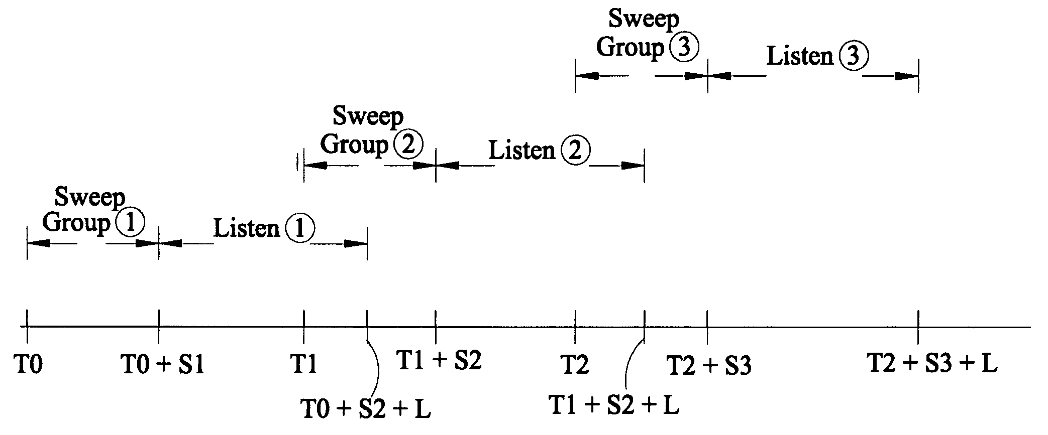
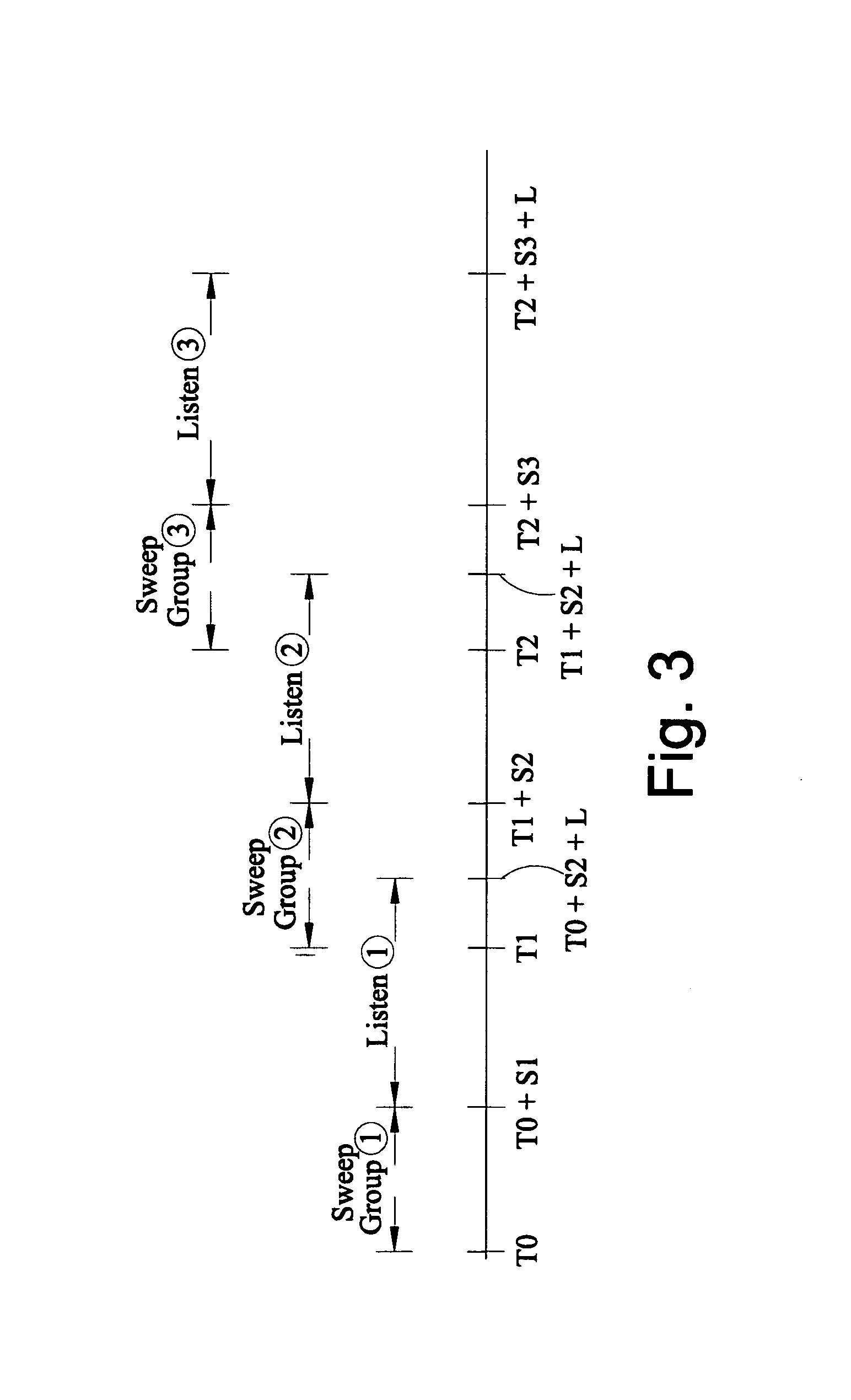
[0014]The present invention provides a method of seismic surveying that combines the known simultaneous acquisition technique and the known slip-sweep acquisition technique. It makes use of the simultaneous acquisition technique in that at least one of the groups of vibrators contains two or more vibrators, but the different groups are swept using a slip-sweep technique. The present invention provides a reduction in the time required to carry out a seismic survey compared to the time required by a conventional slip-sweep technique.
[0019]This embodiment allows a further noise reduction technique to be applied. The varying time delay between a shot of the first group and the shot of a second group means that harmonic noise will occur at different times in the records of the two shots. The noise may therefore eliminated by appropriately summing the two shot records, on the assumption that each shot record contains the same signal.

Problems solved by technology

This is because it is necessary to generate sufficient energy to illuminate structures deep within the earth, and a single seismic source generally cannot do this.
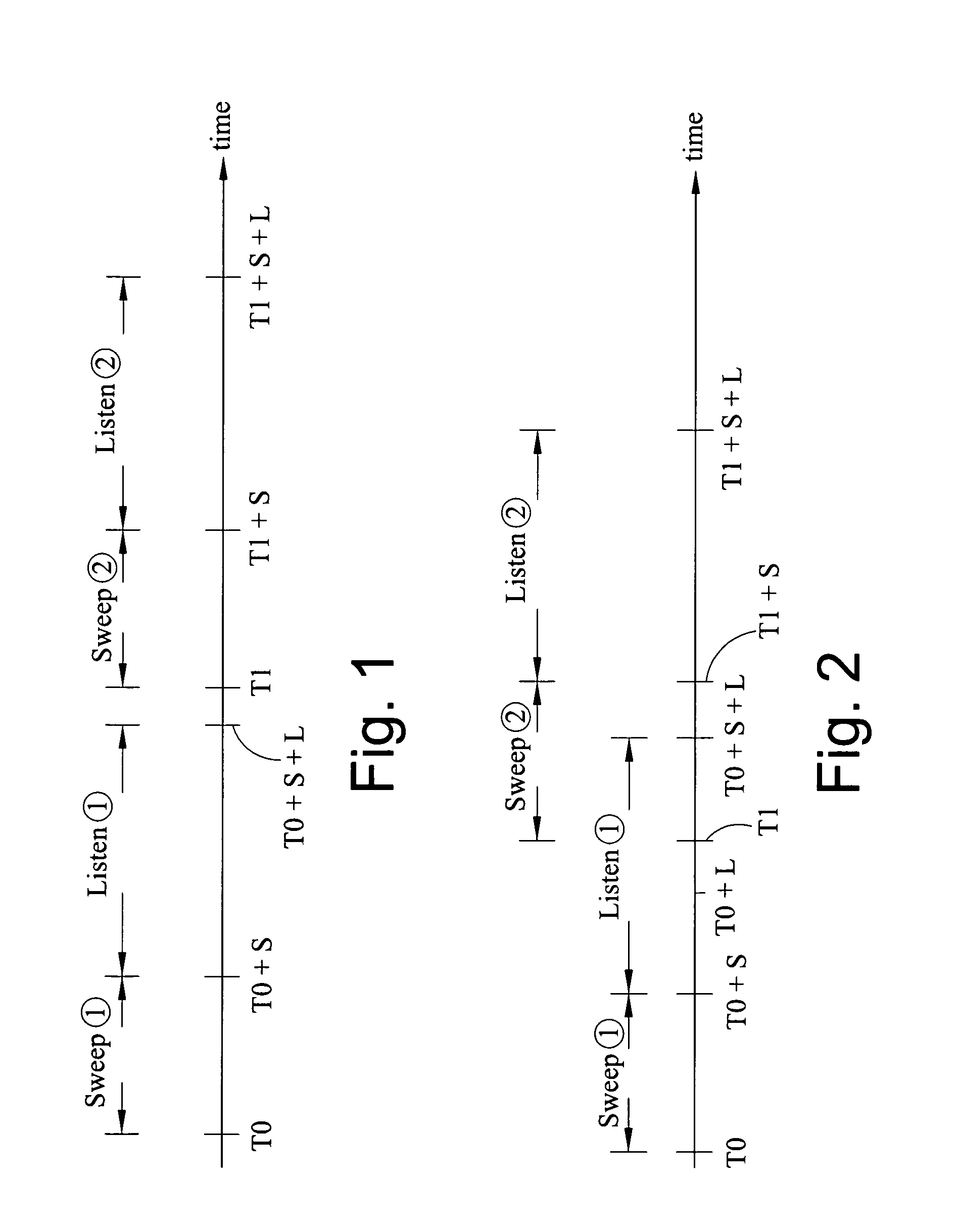
The conventional seismic surveying process has the disadvantage that it can be slow, owing to the need for the minimum time delay between the starts of two vibrator sweeps to be the sum of the sweep time and the listening time.
It has the disadvantage, however, that harmonics of the fundamental frequency generated by one vibrator are present on the seismogram recorded by one or more preceding vibrators.

Method used


Image

  • Method of seismic surveying
  • Method of seismic surveying
  • Method of seismic surveying

Examples


Embodiment Construction

[0037]The operation of a seismic surveying arrangement according to a first embodiment of the present invention is illustrated schematically in FIG. 3, which is a timing diagram of the method. This method enables the time taken to complete a seismic survey to be reduced compared to the conventional slip-sweep method described above.

[0038]The method assumes that the seismic survey has an array of seismic vibrator sources. In order to carry out the method, the vibrators are grouped into two or more groups, with one group of vibrators being operable independently of the or each other group of vibrators. The grouping may be a physical grouping, for example with the vibrators being arranged in a two-dimensional array with each row or column constituting a group. Alternatively the grouping may be a notional grouping, in which vibrators in an array are notionally divided into two or more groups. It is not necessary for each group to have the same number of vibrators, but at least one group...


PUM


Abstract

A method of seismic surveying comprising the steps of actuating the or each vibrator in a first vibrator group at time T0, and subsequently actuating the or each vibrator in a second vibrator group at time T1 that satisfies T0<T1<T0+S1+L where S1 is the sweep time of the first vibrator group and L is the listening time. At least one of the first vibrator group and the second vibrator group comprises at least two vibrators. The first group and the second group of vibrators may be the same group, or they may be different groups. This method enables the time required to complete a seismic survey to be reduced compared to the prior art “simultaneous shooting” and “slip-sweep shooting” techniques.In a case where the first group and the second group of vibrators are different, the method may further comprise actuating the or each vibrator in the first vibrator group at time T2, where T1<T2<T1+S2+L and S2 is the sweep time of the first vibrator group, and then actuating the or each vibrator in the second vibrator group at time T3 where T2<T3<T2+S1+L and where T3−T2≠T1−T0. The varying time delay between a shot of the first vibrator group and the corresponding shot of the second vibrator group means that harmonic noise will occur at different times in the shot records so that the noise may be eliminated by appropriately combining the shot records.

Description

FIELD OF THE INVENTION[0001]The present invention relates to a method of seismic surveying. In particular, it relates to a method of seismic surveying in which two or more groups of vibrator sources emit seismic energy in such a way that their sweep times overlap with one another.BACKGROUND OF THE INVENTION[0002]The principle of seismic surveying is that a source of seismic energy is caused to produce seismic energy that propagates downwardly through the earth. The downwardly-propagating seismic energy is reflected by one or more geological structures within the earth that act as partial reflectors of seismic energy. The reflected seismic energy is detected by one or more sensors (generally referred to as “receivers”). It is possible to obtain information about the geological structure of the earth from seismic energy that undergoes reflection within the earth and is subsequently acquired at the receivers.[0003]In practice, a seismic surveying arrangement comprises an array of sourc...

Claims


Application Information

Patent Timeline
Patent Type & Authority Patents(United States)
IPC IPC(8): G01V1/143G01V1/00
CPCG01V1/005
Inventor JEFFRYES, BENJAMIN PETER
Owner WESTERNGECO LLC
Learn More