Method and apparatus for reducing clock frequency during low workload periods

a clock frequency and low workload technology, applied in the field of processors, can solve the problems of high power dissipation of modern processors, general increase in power dissipation of processors (and other ic devices), and general undesirable high power dissipation

Inactive Publication Date: 2006-05-23
INTEL CORP
View PDF13 Cites 20 Cited by
  • Summary
  • Abstract
  • Description
  • Claims
  • Application Information

AI Technical Summary

Problems solved by technology

As is well known, the power dissipation of a processor (and other IC devices) generally increases with operating frequency.
As a result, these modern processors exhibit relatively high power dissipation.
High power dissipation is generally undesirable and can be especially problematic in battery-powered applications.
Clock throttling tends to reduce the performance of the processor since the clock frequency is reduced even when the processor is trying to perform useful work.
In addition, current clock throttling solutions are relatively coarse (i.e., take a relatively large number of clock cycles to enter the reduced clock frequency mode and to return to the normal clock frequency mode).
The lower supply voltage tends to slow the switching speed of the transistors in the processor, which in turn tends to reduce the performance of the processor.
In addition, the lower supply voltage may undesirable increase the processor's noise sensitivity.
Further, like clock throttling, changing the supply voltage is a relatively coarse power conservation technique.
For example, lowering the voltage by 20% would lower the power by 49%, while hurting the performance (clock rate) by only 20%.
The limitation is that it takes many millions of clock cycles to stabilize a new voltage on an IC.
However, for purely power conservation applications, these shortcomings may be unacceptable.

Method used


Image

  • Method and apparatus for reducing clock frequency during low workload periods
  • Method and apparatus for reducing clock frequency during low workload periods
  • Method and apparatus for reducing clock frequency during low workload periods

Examples


Embodiment Construction

[0014]Embodiments of the present invention are described below in the context of power management of a processor; however, in light of the present disclosure, those of ordinary skill in the art will understand that the present description is generally applicable to all types of IC devices.

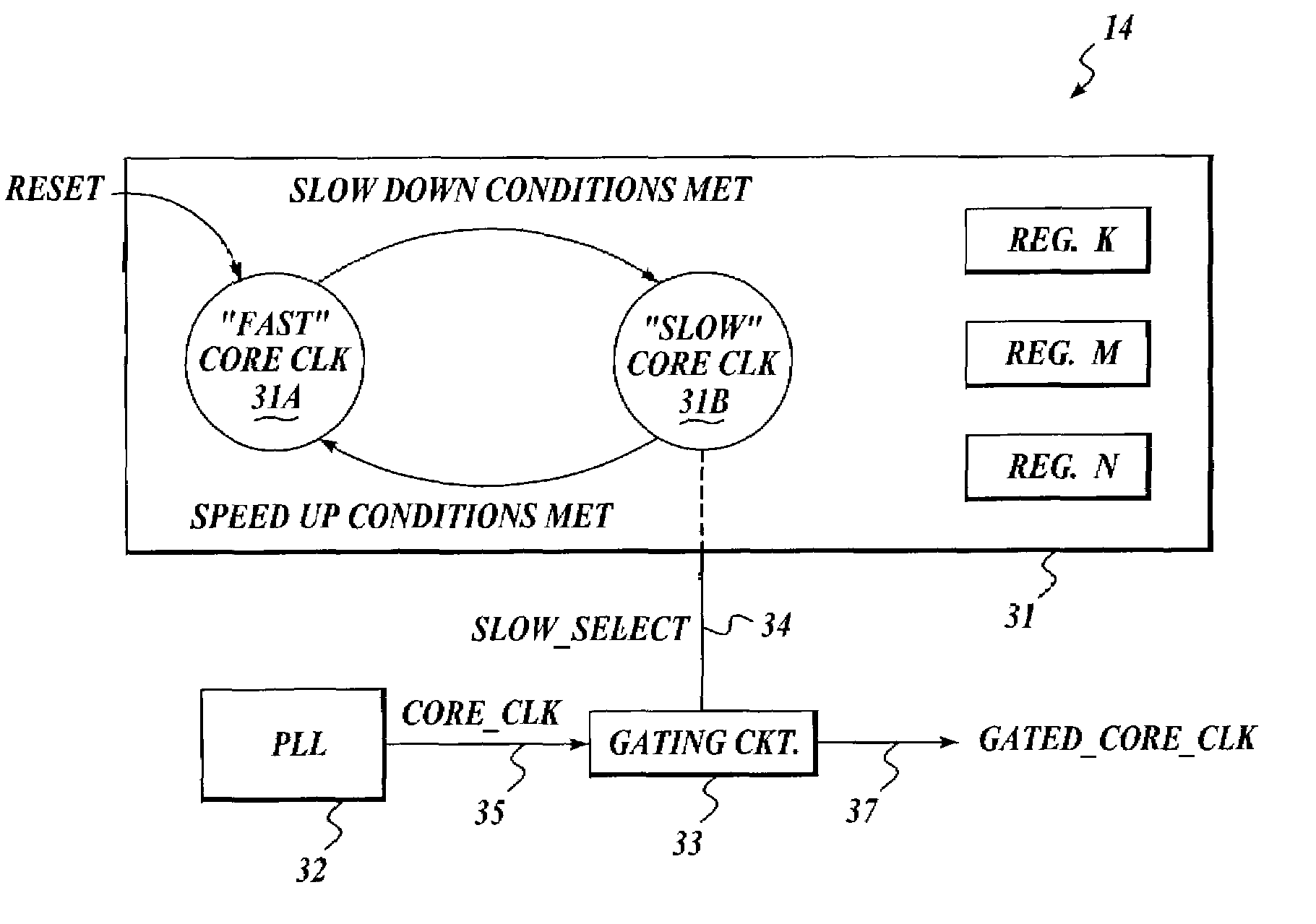
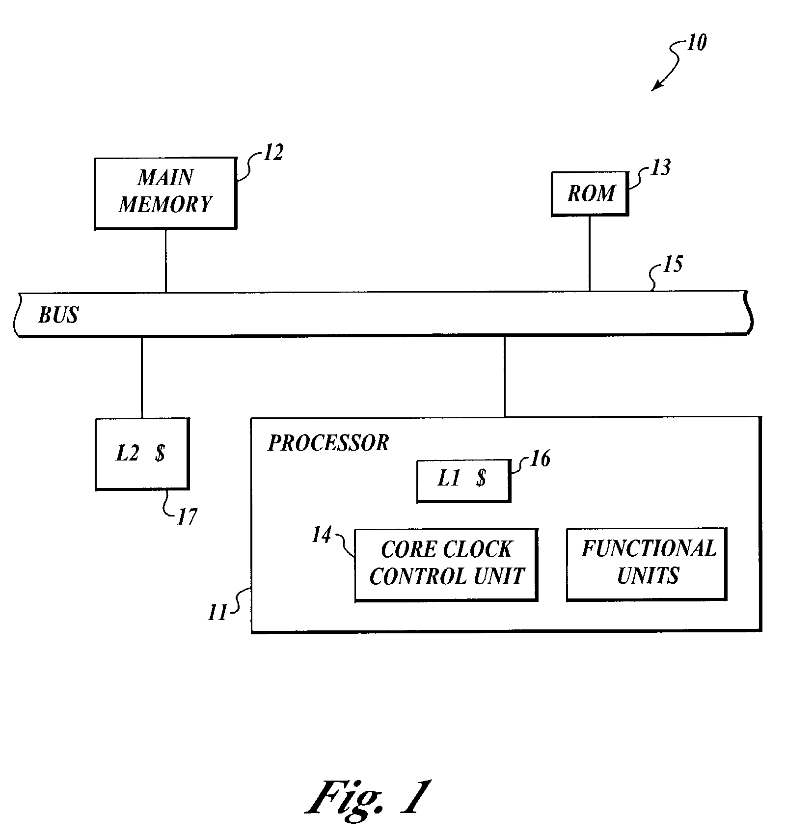
[0015]FIG. 1 illustrates a computer system 10 having a processor 11 with a clock frequency control unit 14, according to one embodiment of the present invention. This embodiment of computer system 10 also includes a main memory 12, a read only memory (ROM) 13, a core clock a bus 15, a first level or internal cache 16 (embedded in processor 11), and a second level or external cache 17. In some embodiments, the second level cache is integrated with the processor and / or there may be other levels of caches either internal or external. Embodiments of clock frequency control unit 14 are described in more detail below in conjunction with FIGS. 3–8.

[0016]Processor 11 is coupled via a bus 15 to main memory ...


PUM


Abstract

A clock frequency control unit for an integrated circuit (IC) includes a clock generator, a finite state machine (FSM), and a gating circuit (GC). The FSM has at least first and second states corresponding to non-low workload low workload states, respectively. In the first state, the GC provides a clock signal to functional units of the IC with the same frequency as the clock generator output. In the second state, the GC reduces the frequency of the clock signal. In one embodiment, the GC masks out selected cycles of the clock generator output to reduce the clock signal frequency. The FSM monitors the operation of the IC to transition from the first state to the second state when selected “low workload” conditions are detected (e.g., long latency cache miss). Similarly, the FSM transitions from the second state to the first state when selected “non-low workload” conditions are detected.

Description

FIELD OF THE INVENTION[0001]Embodiments of the present invention relate to processor and, more particularly but not exclusively, to clock circuits for use in processors.BACKGROUND INFORMATION[0002]A semiconductor integrated circuit (IC) device, such as a processor, may include circuitry of many types of discrete circuit components, including transistors, resistors, and capacitors, as well as other components. Semiconductor IC manufacturers are subject to ever-increasing pressure to increase the speed (i.e. the clock rate) and performance of such IC devices while reducing package size and maintaining reliability. Thus, by way of example, a modern processor (e.g., general purpose microprocessors, digital signal processors, microcontrollers, etc.) may be implemented in a die that includes literally millions of closely spaced transistors and other discrete sub-micron components and operating at clock rates in the GHz range. As is well known, the power dissipation of a processor (and oth...

Claims


Application Information

Patent Timeline
Patent Type & Authority Patents(United States)
IPC IPC(8): G06F1/08G06F1/26G06F1/32
CPCG06F1/3203G06F1/324Y02B60/1217Y02D10/00
Inventor KAZACHINSKY, ITAMAR S.ORENSTEIN, DORON
Owner INTEL CORP
Why Eureka
Try Eureka