
Three in one combined power unit for nitrogen system, fluid system, and coiled tubing system

a technology of nitrogen system and fluid system, which is applied in the direction of drilling casings, drilling pipes, borehole/well accessories, etc., can solve the problems of doubling the number of personnel required to run the service, doubling the transportation cost, and doubling the number of personnel required

Inactive Publication Date: 2006-05-30
P E T INT
View PDF13 Cites 14 Cited by
  • Summary
  • Abstract
  • Description
  • Claims
  • Application Information

AI Technical Summary

Benefits of technology

[0004]It is an object of this present invention to provide a combined tractor trailer unit which utilizes a single tractor and a single trailer to provide a service for treating wells with a combined tractor trailer unit through which gaseous nitrogen can be pumped.

Problems solved by technology

Because of the duplicity of the tractor trailer units, this has caused a doubling of the transportation costs, a doubling of the personnel required to have the units arrive at the well, and a doubling of the number of personnel required to run this service.

Method used


Image

  • Three in one combined power unit for nitrogen system, fluid system, and coiled tubing system
  • Three in one combined power unit for nitrogen system, fluid system, and coiled tubing system
  • Three in one combined power unit for nitrogen system, fluid system, and coiled tubing system

Examples


Embodiment Construction

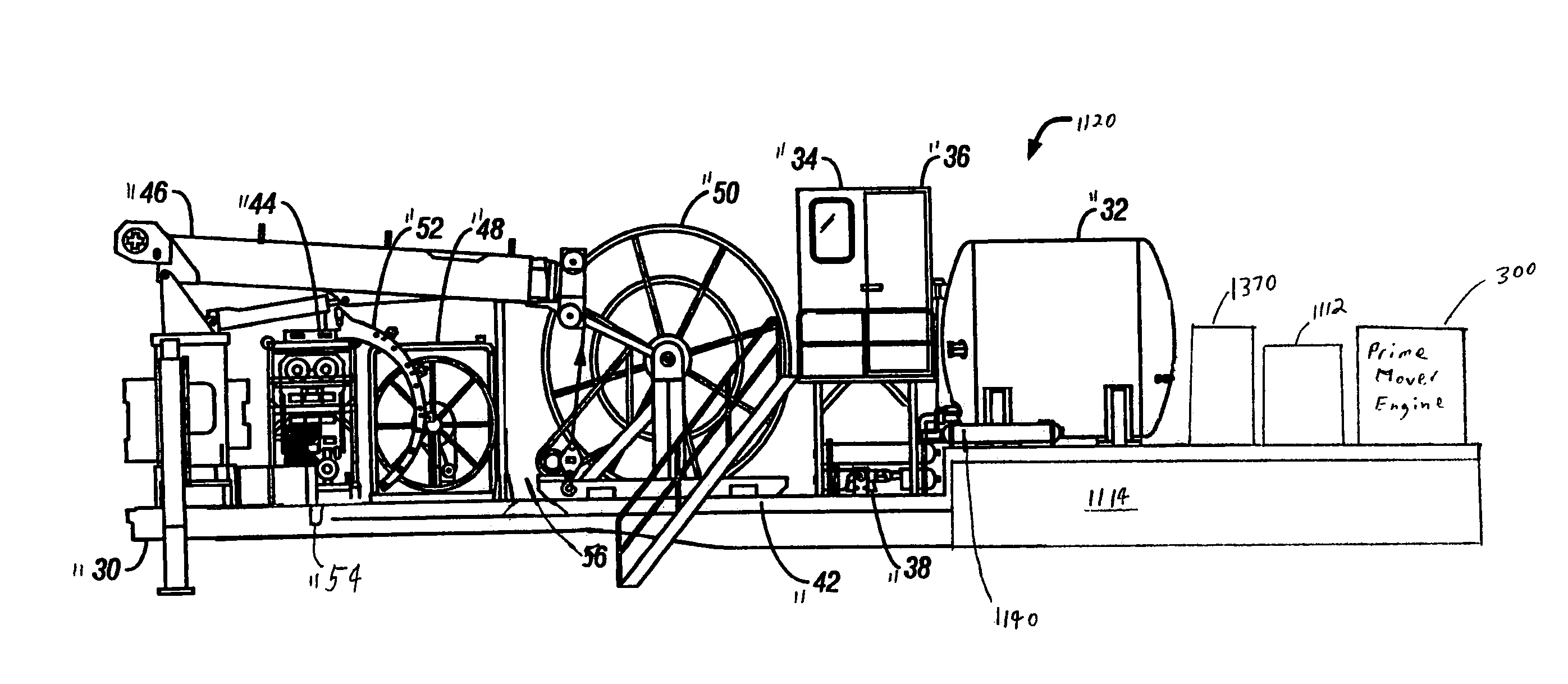
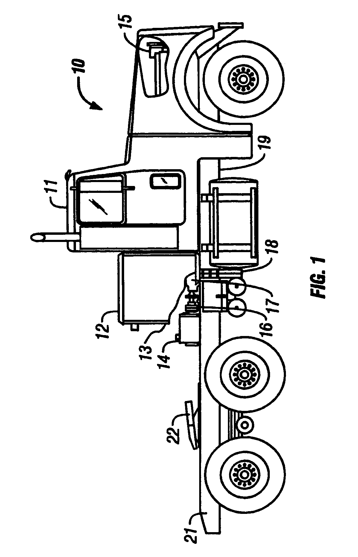
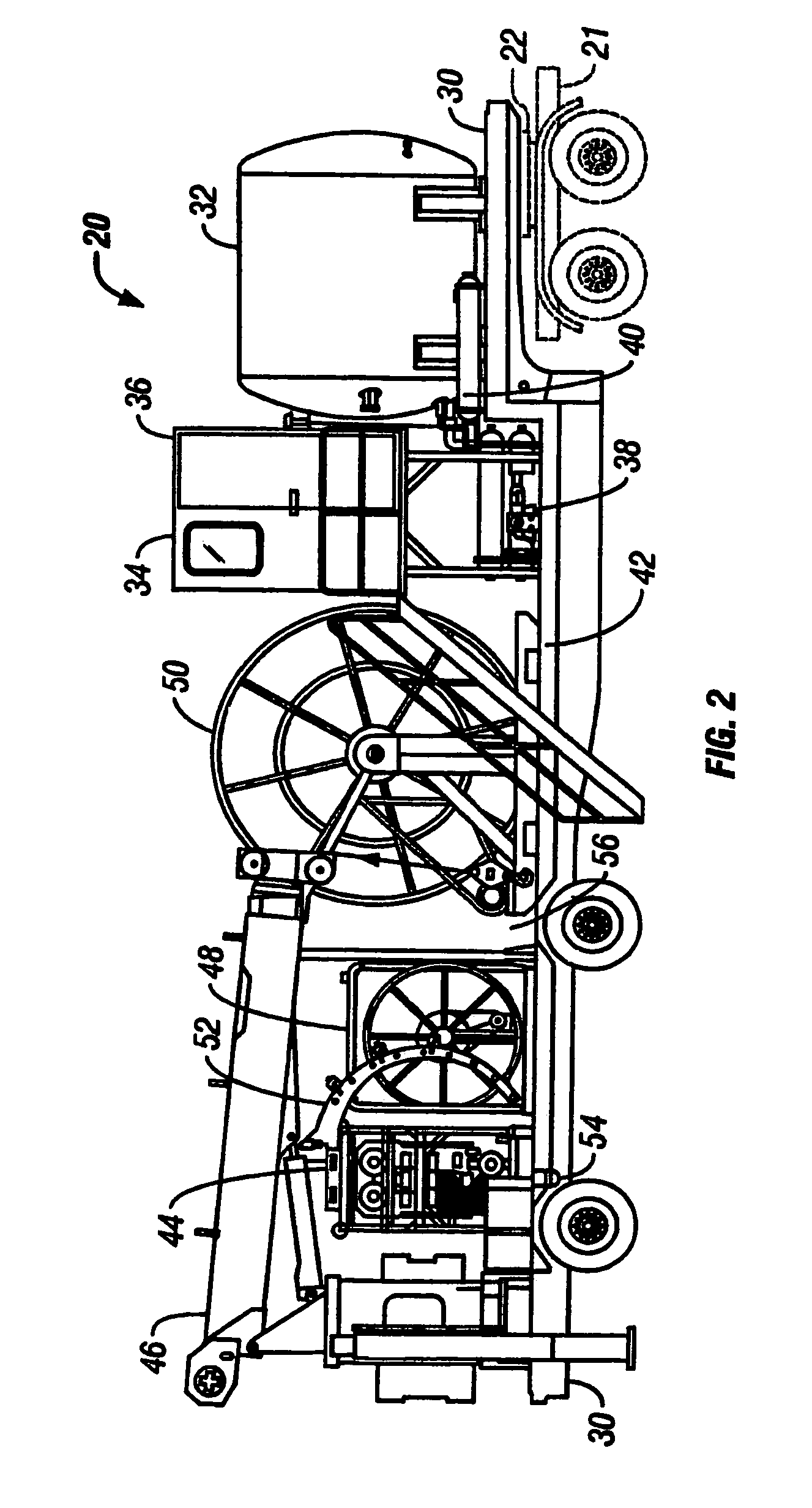
[0019]Referring now to FIG. 1, a tractor 10 having either a gasoline engine or a diesel engine is illustrated and which is used to pull the trailer 20 illustrated in FIG. 2 and which also uses its engine to drive all of the components which are illustrated in FIG. 1. and FIG. 2, on the tractor 10, and the trailer 20, respectively. The chassis 11 of the tractor 10 may be, for example, a Freightliner. The tractor 10 also has a hydraulic tank 12 and a tank holddown unit 13 which secures the hydraulic tank to the chassis. A hydraulic pump 14 has a coupling and a drive mechanism connected to its one end. The coupling 16 is connected into a transfer case and drive shaft mechanism 17. A hydraulic pump 18 is one of many hydraulic pumps in the tractor assembly 10 and also includes various hydraulic pumps within the assembly 19. It should be appreciated that all of the mechanisms illustrated with the tractor 20 in FIG. 2 are driven by hydraulic pumps located on the tractor chassis 10. The ass...


PUM


Abstract

A single tractor unit is provided for pulling a trailer, in which the tractor itself drives a plurality of hydraulic motors which control a crane unit, a coiled tubing injection unit, and the pumps and motors associated with a liquid nitrogen system which is used for injecting gaseous hydrogen into a workover well with coiled tubing. In an alternative mode, the liquid nitrogen system is replaced with nitrogen generators or tanks of compressed nitrogen gas. In another alternative embodiment, a separate engine, preferably mounted with the other equipment on a trailer, skid, or barge, replaces the single tractor engine for driving the plurality of hydraulic motors. In yet another embodiment, a single engine drives a plurality of well treating systems on an off-shore installation.

Description

RELATED APPLICATION[0001]This application is a second Continuation-in-Part of U.S. patent application Ser. No. 10 / 127,092, filed Apr. 22, 2002 now U.S. Pat. No. 6,702,011, for “Combined Nitrogen Treatment System and Coiled Tubing System In One Tractor / Trailer Apparatus”.FIELD[0002]This invention relates, generally, to the treatment of oil and gas wells using nitrogen to increase the production capability of the wells, and specifically, to providing on a single trailer / skid combination, all of the equipment accessories to pump nitrogen through a coiled tubing into the wells being treated and a single prime mover power source for operating such equipment.BACKGROUND OF THE INVENTION[0003]It is known in the art to provide work over operations using gaseous nitrogen to remove sand and / or water or other impediments to production. The prior art has not recognized that a single trailer or skid unit, with a single prime power source, can be provided with all of the equipment and accessories ...

Claims


Application Information

Patent Timeline
IPC IPC(8): E21B19/22E21BE21B17/20E21B19/00E21B43/16
CPCE21B15/00E21B43/168E21B19/22E21B17/203
Inventor CRAWFORD, JAMES B.LAMB, EDWARD R.
Owner P E T INT
Learn More