Rotary machine with seal

a rotary machine and seal technology, applied in machines/engines, mechanical devices, liquid fuel engines, etc., can solve the problems of increasing the clearance, and reducing the sealing performance of the comb-type sealing device, etc., to achieve the effect of suppressing the reduction of the sealing performan

Inactive Publication Date: 2006-05-30
KK TOSHIBA
View PDF25 Cites 33 Cited by
  • Summary
  • Abstract
  • Description
  • Claims
  • Application Information

AI Technical Summary

Benefits of technology

[0015]The present invention has been made in view of the foregoing problems and it is therefore an object of the present invention to provide a rotary machine provided with a sealing device capable of suppressing the reduction of sealing performance resulting from the relative axial displacement of a rotary member and a stationary member due to the difference between the rotary member and the stationary member in thermal expansion.

Problems solved by technology

When the sealing fins F1 and F2 are displaced axially relative each other due to the difference in thermal expansion between the rotor and the casing, the clearances increase and the sealing performance of the comb-type sealing device deteriorates sharply.
However, the possible number of stages of the sealing fins is limited because the blowby of the fluid flowing in a sealing part occurs if the number of the stages of the fins is greater than a certain limit.
However, it is possible that the edges of the fins 7 and 8 come into contact with the rotating members 1 and 2, and there by the fins 7 and 8, and the rotating members 1 and 2 are damaged if the clearances are excessively small.
The variation of the clearances due to thermal deformation during the operation of the rotary machine is the principal factor of such a trouble resulting from contact between the members.
Therefore, if the size of the clearance is determined on the basis of conditions for operations other than those for the rated operation of the rotary machine, the clearances increase unnecessarily during the rated operation and, consequently, the leak rate of the working fluid increases.
Thus, those movable sealing mechanisms are not provided with any measures for coping with the relative axial displacement of the casing and the rotor due to the difference between the casing and the rotor in thermal expansion (thermal elongation).
The axial arrangement of the ridges at big pitches reduces working fluid sealing effect.

Method used


Image

  • Rotary machine with seal
  • Rotary machine with seal
  • Rotary machine with seal

Examples


first embodiment

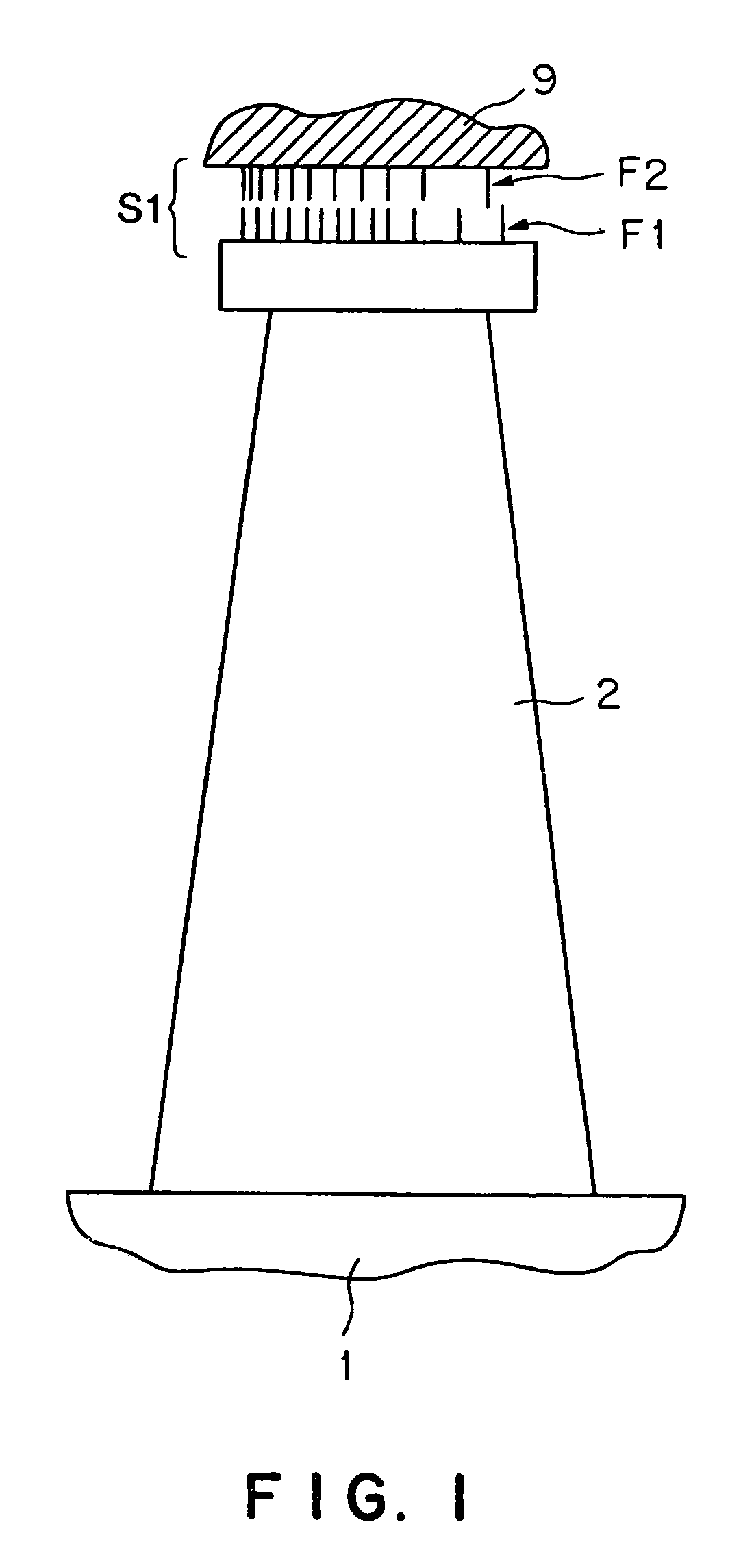
[0044]A rotary machine in a first embodiment according to the present invention will be described with reference to FIG. 1. FIG. 1 shows an essential part of the rotary machine in the first embodiment, such as an axial-flow turbine. The rotary machine has a rotor 1 supported for rotation about an axis of rotation and provided with a rotor blade 2, i.e. a rotating member, and a labyrinth packing 9, i.e. a stationary member, surrounding the rotor 1. The labyrinth packing 9 is held on an outer ring 3 of a nozzle diaphragm mounted on a casing 6 (FIGS. 8 and 9). A comb-type labyrinth sealing device S1 is disposed in a gap between the outer edge of the rotor blade 2 and the labyrinth packing 9.

[0045]The labyrinth sealing device S1 has a plurality of sealing fins F1 and F2 arranged opposite to each other on the opposite sides of the gap, respectively. The sealing fins F1 and F2 are axially spaced apart at unequal pitches. More specifically, the sealing fins F1 and F2 of the rotary machine ...

second embodiment

[0052]A rotary machine in a second embodiment according to the present invention will be described with reference to FIG. 4. The rotary machine in the second embodiment is provided with a labyrinth sealing device S2. The labyrinth sealing device S2 is the same in construction as the labyrinth sealing device S1 in the first embodiment shown in FIG. 1, except that the labyrinth sealing device S2 differs from the labyrinth sealing device S1 in the arrangement of its sealing fins F1 and F2.

[0053]In the sealing device S2 included in the rotary machine in the second embodiment, the sealing fins F1 on the side of a rotor blade 2 are axially spaced apart at unequal pitches such that the pitches decrease from both ends toward the middle of the row of the sealing fins F1. The sealing fins F2 on the side of a labyrinth packing 9 are axially spaced apart at unequal pitches such that the pitches decrease from one end toward the middle of the row of the sealing fins F2, increase in the middle of ...

third embodiment

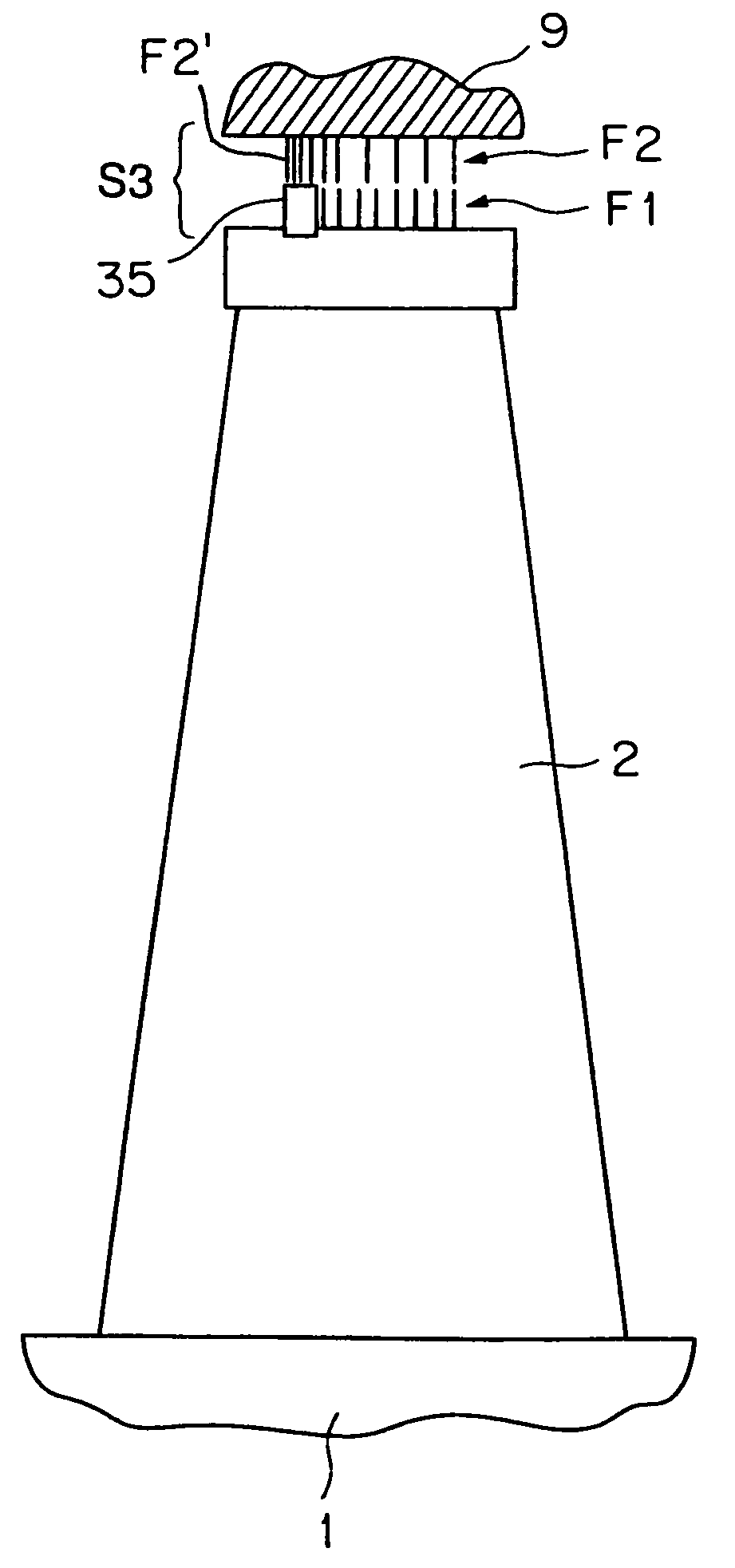
[0056]A rotary machine in a third embodiment according to the present invention will be described with reference to FIG. 5. The rotary machine in the third embodiment is provided with a labyrinth sealing device S3. The labyrinth sealing device S3 differs from the labyrinth sealing device S1 in the first embodiment shown in FIG. 1 in that a ridge 35 is formed in the outer edge of a rotor blade 2 and some of the sealing fins F2 are disposed opposite to the ridge 35. The ridge 35 has a width greater than the thickness of sealing fins F1 and F2 (F2′) along the axis of rotation. The labyrinth sealing device S3 is similar in other respects to the labyrinth sealing device S1 included in the rotary machine in the first embodiment.

[0057]The sealing fins F1 on the rotor blade 2 provided with the ridge 35 are axially space apart substantially at equal pitches. Pitches between the sealing fins F2′ (first sealing fins) opposite to the ridge 35 among the sealing fins F2 are smaller than those bet...


PUM


Abstract

The so-called comb-type labyrinth sealing device (S1) is disposed in a gap between a rotor blade (2), i.e. a rotating member, and a labyrinth packing (9), i.e. a stationary member. The sealing device (S1) has a plurality of sealing fins (F1, F2) arranged on the opposite sides of the gap opposite to each other. The sealing fins are axially spaced apart at unequal pitches, and hence a possibility that some of the clearances between the opposite sealing fins (F1, F2) decrease when a casing holding the labyrinth packing (9) and a rotor (1) are axially displaced relative to each other due to the difference in thermal expansion between the rotator and the casing increases.

Description

TECHNICAL FIELD[0001]The present invention relates to a rotary machine, such as an axial-flow turbine, and, more particularly, to improvements in a sealing device between stationary and rotating members of a rotary machine.BACKGROUND ART[0002]It has been desired to reduce, to the least possible extent, the leak rate of a working fluid that leaks through gaps between stationary and rotating members of rotary machines, such as axial-flow turbines including steam turbines and gas turbines.[0003]FIG. 8 shows a general steam turbine, i.e. a rotary machine. This steam turbine has a turbine rotor 1 provided with rotor blades 2, i.e. rotating members, and a turbine casing 6 enclosing outer rings 3 of a nozzle diaphragm, stator blades (turbine nozzles) 4, and inner rings 5 of a nozzle diaphragm, i.e. stationary members. Opposite ends of the rotor 1 are supported in bearings 11. Noncontact sealing devices are interposed between each of the rotor blades 2 and each of the outer rings 3, and bet...

Claims


Application Information

Patent Timeline
Patent Type & Authority Patents(United States)
IPC IPC(8): F16J15/447F01D11/08F02C7/28
CPCF16J15/4472F05C2251/08
Inventor UCHIDA, TATSUROKIKUCHI, MASATAKA
Owner KK TOSHIBA
Why Eureka
Try Eureka