
Electric arc welder system with waveform profile control

a technology of waveform and welder, which is applied in the direction of arc welding apparatus, welding apparatus, manufacturing tools, etc., can solve the problems of inability to accurately and varied shape accurately produced by scr welders, and achieve the effect of reducing the number of welds

Active Publication Date: 2006-05-30
LINCOLN GLOBAL INC
View PDF8 Cites 19 Cited by
  • Summary
  • Abstract
  • Description
  • Claims
  • Application Information

AI Technical Summary

Problems solved by technology

In the past, the ability to use SCR welders to produce AC waveforms of accurately and varied shapes is technically difficult, if not impossible.

Method used


Image

  • Electric arc welder system with waveform profile control
  • Electric arc welder system with waveform profile control
  • Electric arc welder system with waveform profile control

Examples


Embodiment Construction

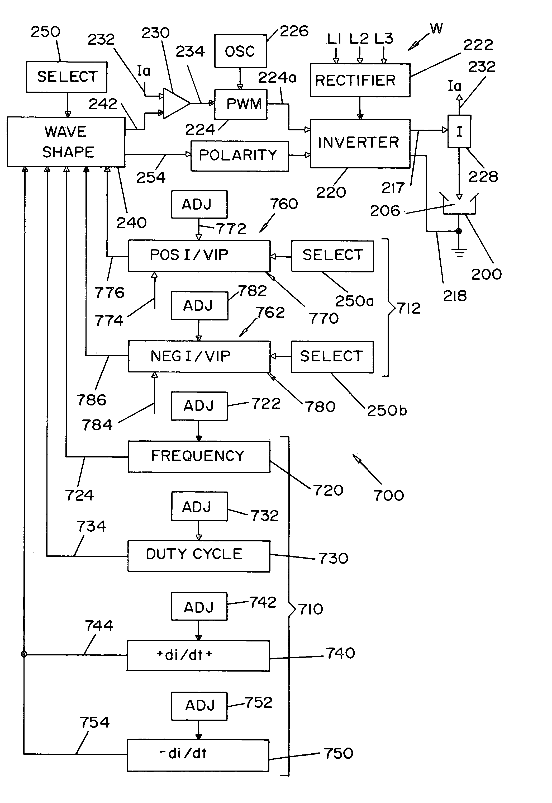
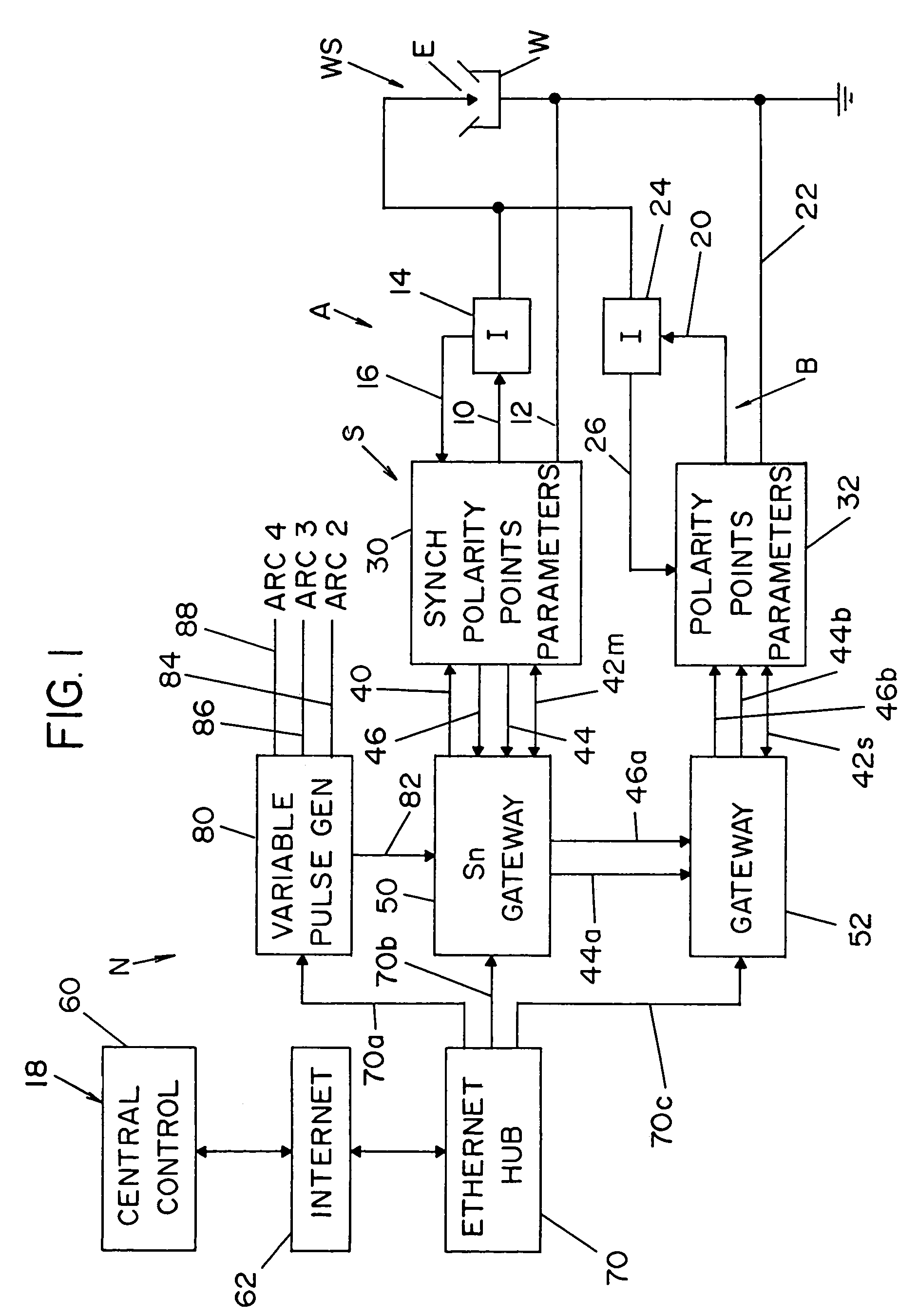
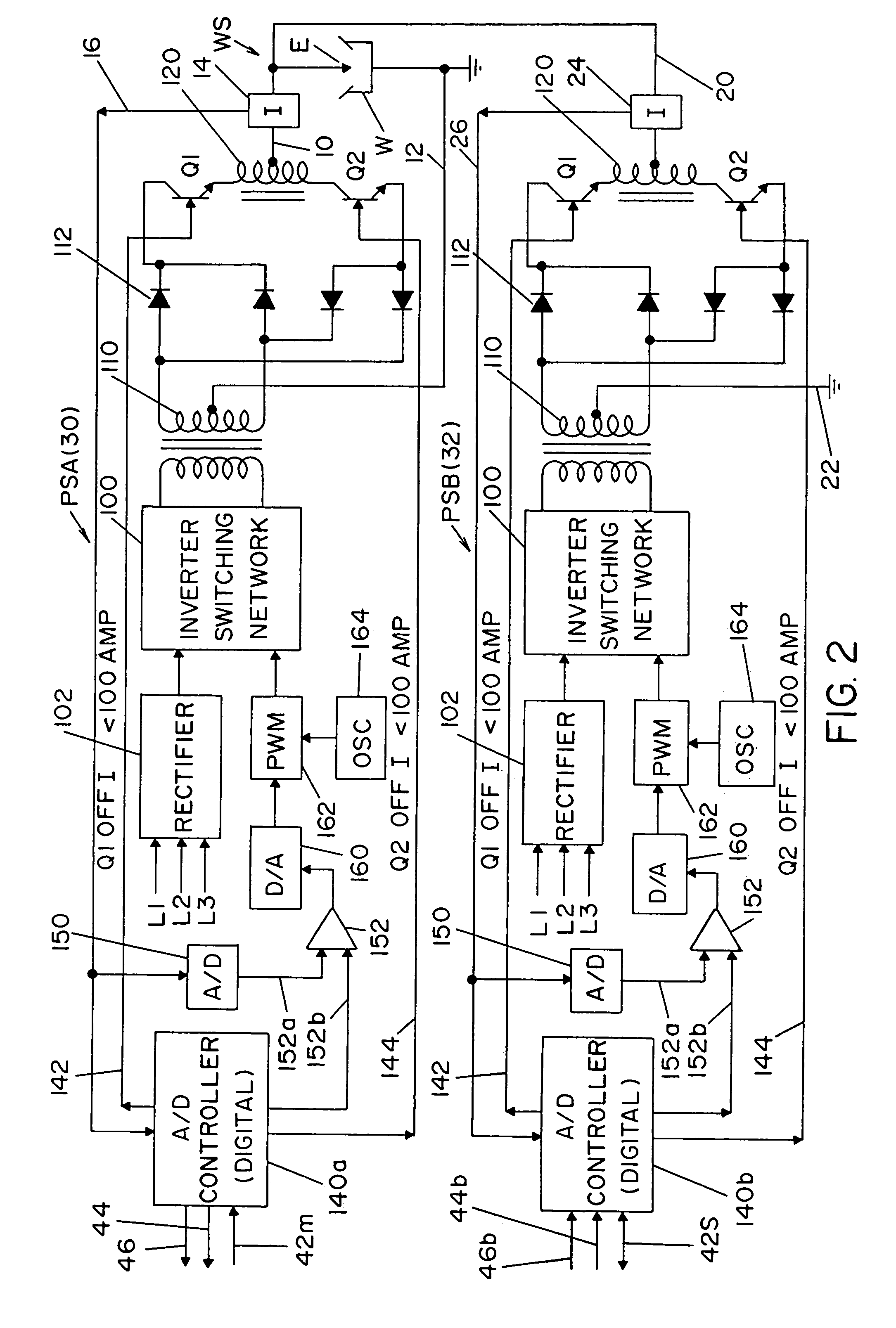
[0037]Referring now to the drawings wherein the showings are for the purpose of illustrating a preferred embodiment of the invention only and not for the purpose of limiting same, a background system for implementing the invention is shown in detail in FIGS. 1, 2, 4, 5 and 16. FIGS. 2 and 6–15 describe prior attributes of the disclosed background welding systems. The improvement of this invention is shown in FIGS. 17 and 18.

[0038]Turning now to the background system to which the present invention is an improvement and / or an enhancement, FIG. 1 discloses a single electric arc welding system S in the form of a single cell to create an alternating current as an arc at weld station WS. This system or cell includes a first master welder A with output leads 10, 12 in series with electrode E and workpiece W in the form of a pipe seam joint or other welding operation. Hall effect current transducer 14 provides a voltage in line 16 proportional to the current of welder A. Less time critical ...


PUM

PropertyMeasurementUnit
frequencyaaaaaaaaaa
currentaaaaaaaaaa
timeaaaaaaaaaa

Abstract

An electric arc welder for creating a succession of AC waveforms between an electrode and workpiece by a power source comprising an high frequency switching device for creating individual waveforms in the succession of waveforms. Each of the individual waveforms has a profile determined by the magnitude of each of a large number of short current pulses generated at a frequency of at least 18 kHz by a pulse width modulator with the magnitude of the current pulses controlled by a wave shaper. The welder is provided with a profile control network for setting more than one profile parameter selected from the class consisting of frequency, duty cycle, up ramp rate and down ramp rate and a magnitude circuit for adjusting the waveform profile to set total current, voltage and / or power.

Description

[0001]The present invention relates to the art of electric arc welding and more particularly to an electric arc welder with waveform profile control.INCORPORATION BY REFERENCE[0002]The present invention is directed to an electric arc welder system utilizing high capacity alternating circuit power sources for driving two or more tandem electrodes of the type used in seam welding of large metal blanks. It is preferred that the power sources use the switching concept disclosed in Stava U.S. Pat. No. 6,111,216 wherein the power supply is an inverter having two large output polarity switches with the arc current being reduced before the switches reverse the polarity. Consequently, the term “switching point” is a complex procedure whereby the power source is first turned off awaiting a current less than a preselected value, such as 100 amperes. Upon reaching the 100 ampere threshold, the output switches of the power supply are reversed to reverse the polarity from the D.C. output link of ...

Claims


Application Information

Patent Timeline
Patent Type & Authority Patents(United States)
IPC IPC(8): B23K9/09
CPCB23K9/092
Inventor STAVA, ELLIOTT K.
Owner LINCOLN GLOBAL INC
Learn More