Semiconductor device

a semiconductor and shielding technology, applied in the details of semiconductor/solid-state devices, semiconductor devices, electrical apparatus, etc., can solve the problems of increasing the size of semiconductor devices, affecting the spiral inductor by noise and unnecessary signals, and affecting so as to achieve the effect of not impairing the flexibility of wiring layou

Active Publication Date: 2006-05-30
GK BRIDGE 1
View PDF6 Cites 0 Cited by
  • Summary
  • Abstract
  • Description
  • Claims
  • Application Information

AI Technical Summary

Benefits of technology

[0009]Therefore, with the foregoing in mind, it is an object of the present invention to provide a semiconductor device having a shielding structure that is free from the influence of noise and an unnecessary signal even when a connection terminal adjacent to a spiral inductor is not a low impedance terminal and that does not impair the flexibility of wiring layout.

Problems solved by technology

In the configuration like the conventional example, however, in the case where any one of the connection terminals 2a to 2c functions as an input / output terminal through which an electrical signal passes or a connection terminal with high impedance, the spiral inductor is affected by noise and an unnecessary signal.
This imposes a considerable restriction on a layout configuration of the semiconductor device, which results in an increase in size of the semiconductor device.
Additionally, this configuration imposes a restriction on a low-impedance wiring such as the ground also, so that the flexibility of wiring layout, which is an advantage of the multilayered wiring structure, is impaired, thus resulting in an increase in size of the semiconductor device.

Method used


Image

  • Semiconductor device
  • Semiconductor device
  • Semiconductor device

Examples


embodiment 1

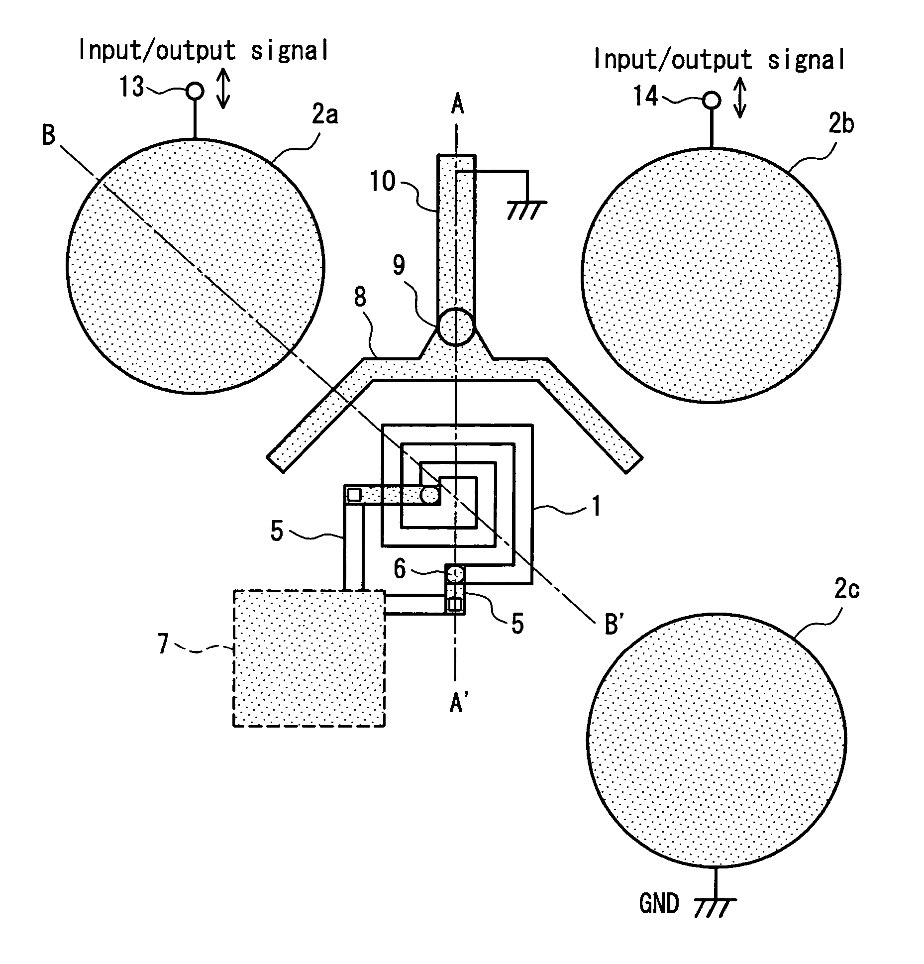
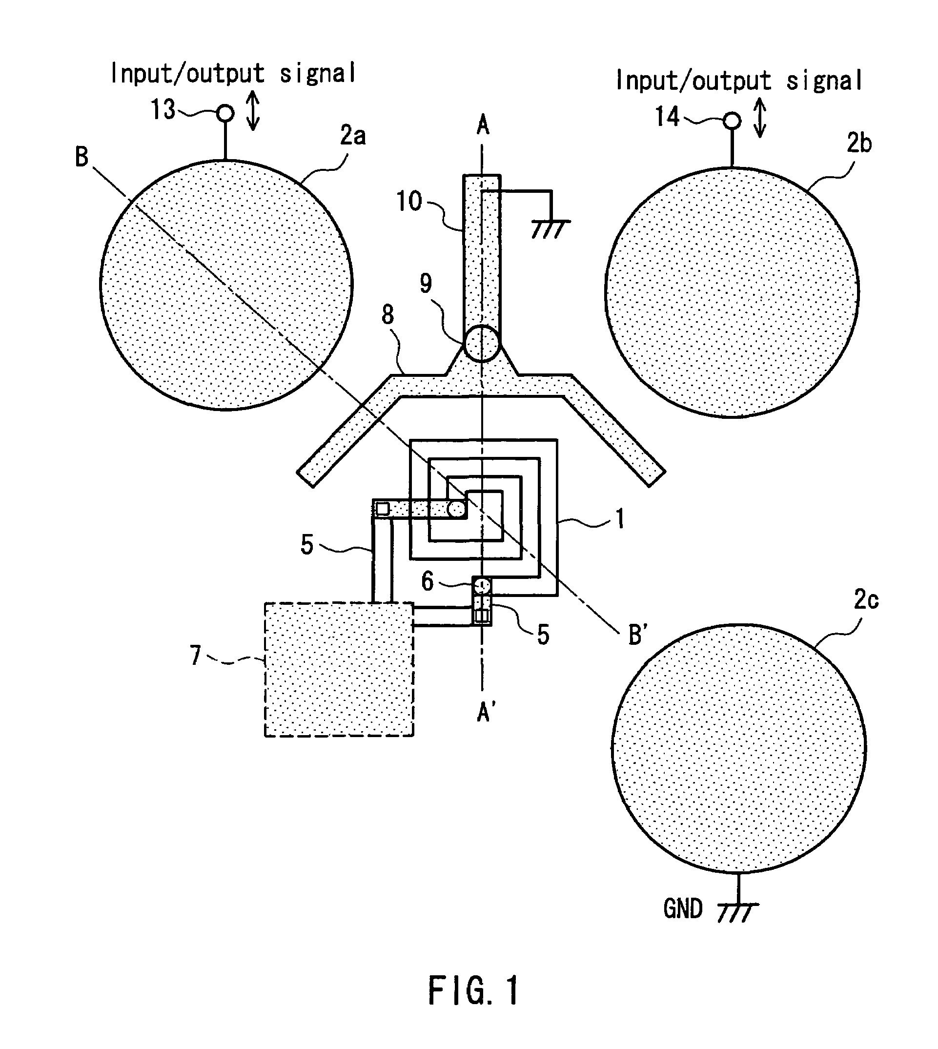
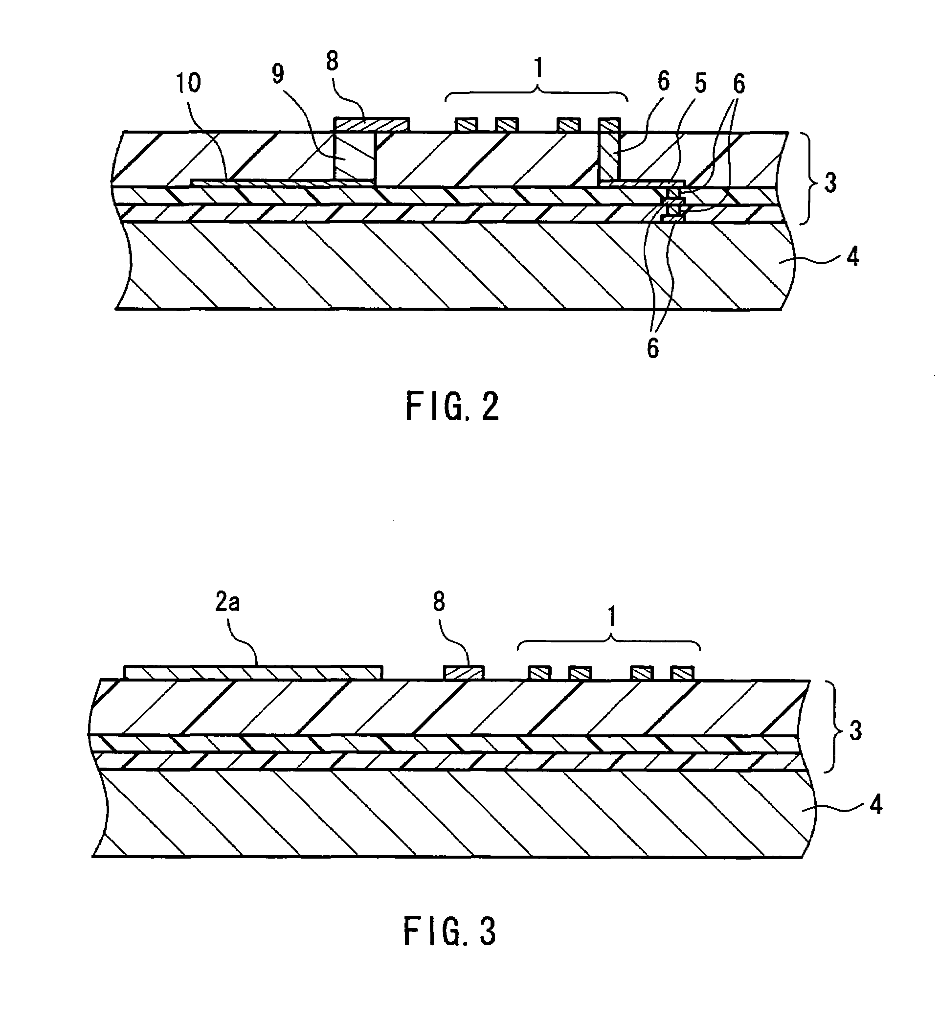
[0025]FIGS. 1 to 3 show a semiconductor device according to Embodiment 1. FIG. 1 is a top plan view of the semiconductor device. FIG. 2 is a cross-sectional view taken along line A–A′ of FIG. 1 and FIG. 3 is a cross-sectional view taken along line B–B′ of FIG. 1. In the following descriptions, the same reference numerals are assigned to the same elements as those in the conventional example.

[0026]In FIG. 1, reference numeral 1 denotes a spiral inductor, around which connection terminals 2a, 2b and 2c leading to a printed board or the like are disposed. The connection terminals 2a and 2b each are connected with input / output terminals 13, 14 for an electrical signal, and the connection terminal 2c is connected with the ground. The spiral inductor 1 is connected with a circuit block 7 by way of a wiring 5 and a via 6 for the interlayer connection of the wiring layer.

[0027]As shown in FIG. 2, the wiring 5 and the via 6 are formed at a multilayered wiring region 3 including a wiring laye...

embodiment 2

[0031]FIG. 4 is a top plan view of a semiconductor device according to Embodiment 2 of the present invention. The same reference numerals are assigned to the same elements as those of Embodiment 1 shown in FIG. 1 so as to simplify the explanations.

[0032]In the present embodiment, as shown in FIG. 4, a spiral inductor 1 and a spiral inductor 11 are arranged to be symmetric with respect to a line. The spiral inductors 1 and 11 are connected with a differential circuit. In the vicinity of the spiral inductor 11, connection terminals 2d and 2e are disposed, through which connection with an external terminal of the semiconductor device is established. Between the spiral inductor 11 and the connection terminals 2d and 2e, a shielding wiring pattern 12 is disposed. The connection terminal 2d is connected with an electrical signal input / output terminal 15, and the connection terminal 2e is connected with the ground and also with the shielding wiring pattern 12.

[0033]The present embodiment h...

embodiment 3

[0036]FIG. 5 is a block diagram of radio equipment according to Embodiment 3 of the present invention. The present embodiment shows one example in which the combination of the spiral inductor and the shielding wiring pattern that are configured similarly to the above-described embodiments is applied to a semiconductor device 27 constituting a part of the radio equipment.

[0037]A signal is input from the outside to the semiconductor device 27 by way of an antenna 21, a transfer switch 22, a low noise amplifier 23, a filter 24, a power amplifier 25 and a filter 26, and a signal is output to the outside from the semiconductor device 27. The semiconductor device 27 is made up of an amplifier 28, a gain control amplifier 29, a mixer 30, a local part 31, a base band processing part 32 and the like. The semiconductor device 27 performs input / output of signals with respect to a control processing part 33. The control processing part 33 is connected with a display part 34, an input part 35, a...


PUM


Abstract

A semiconductor device includes: a semiconductor substrate in which a semiconductor element is formed; a multilayer structured wiring layer that is provided on the semiconductor substrate, the wiring layer forming a structure connected with the semiconductor element; a spiral inductor that is formed in at least one layer of the wiring layer; and a connection terminal formed in an uppermost layer of the wiring layer for establishing connection from the wiring layer to an outside such as a printed board. A shielding wiring pattern is disposed between the spiral inductor and the connection terminal, the shielding wiring pattern functioning as an electromagnetic shield for the uppermost layer of the wiring layer. The shielding wiring pattern absorbs a change in electrical field caused by a potential change in the connection terminal, providing a shielding structure which suppresses the superposing of noise and an unnecessary signal onto the spiral inductor from the connection terminal.

Description

FIELD OF THE INVENTION[0001]The present invention relates to an electromagnetic shielding structure for a spiral inductor formed in a semiconductor device.BACKGROUND OF THE INVENTION[0002]In recent years, along with the progress of a semiconductor device with a higher integration degree and a higher density, a semiconductor device with a built-in inductance passive element, which was connected externally as a separate element in an earlier device, has become commercially practical. Such a highly integrated semiconductor device is required to satisfy mutually contradictory conditions so as to prevent the superposing of noise and an unnecessary signal on an electrical signal of a circuit and to allow for the arrangement of input / output wirings and terminals for a large number of circuit blocks that are highly integrated.[0003]Referring to FIGS. 6 to 8, a configuration of a conventional semiconductor device with a built-in spiral inductor will be described below. FIG. 6 is a plan view,...

Claims


Application Information

Patent Timeline
Patent Type & Authority Patents(United States)
IPC IPC(8): H01L29/00H01L23/552H01L21/822H01L23/522H01L27/04H01L27/08H01Q1/38
CPCH01L23/5225H01L23/5227H01L27/08H01Q1/38H01L2924/3011H01L2924/0002H01L2924/00
Inventor FUKUI, TSUKASAISHIDA, KAORU
Owner GK BRIDGE 1
Why Eureka
Try Eureka