Colored resin composition for laser welding and composite molding product using the same

a technology of laser welding and composite molding, which is applied in the direction of organic dyes, special tyres, transportation and packaging, etc., can solve the problems of reducing the transmittivity of laser beams, affecting the flexibility of product design, and affecting the moldability of polybutylene terephthalate based resins, etc., to achieve less stain to the mold, not impairing the flexibility of product design, and dark color tone

Inactive Publication Date: 2005-06-02
TORAY IND INC
View PDF6 Cites 35 Cited by
  • Summary
  • Abstract
  • Description
  • Claims
  • Application Information

AI Technical Summary

Benefits of technology

[0032] The colored resin composition for laser welding of the present invention is suitably used for a molding product on the side of the laser beam transmission because it does not impair flexibility of the product design, has a dark color tone, and gives less stain to the mold upon injection molding.

Problems solved by technology

However, as is described in JP-A-2001-26656, great improvements in laser beam transmittivity are not expected by merely controlling the melting point, therefore, improvement in flexibility upon design of a molding product in connection with the wall thickness cannot be expected.
Also, there have existed problems involving impairment of moldability of the polybutylene terephthalate based resin.
Furthermore, it has been proven that the colorant to be compounded may decrease the laser beam transmittivity, and there have existed technical problems of impossible appearance of a dark color tone, and the like because a colorant must be selectively compounded to achieve favorable laser beam transmittivity.
Moreover, dyes described in JP-A-2000-309694, JP-A-2001-71384, JP-A-2003-136601 have a sublimation and a melting point, therefore, there exist problems involved in staining of the mold upon injection molding, and in thermal stability during retention.

Method used


Image

  • Colored resin composition for laser welding and composite molding product using the same
  • Colored resin composition for laser welding and composite molding product using the same
  • Colored resin composition for laser welding and composite molding product using the same

Examples


example

[0088] Examples are demonstrated below to explain the present invention more specifically, however, the present invention is not limited to the description of these Examples. Further, the ratio of addition and compounding presented in the Examples and Comparative Examples are all based on parts by weight.

[0089] Hereinafter, methods of the evaluation of material characteristics of the Examples and Comparative Examples are demonstrated.

(1) Evaluation of Moldability

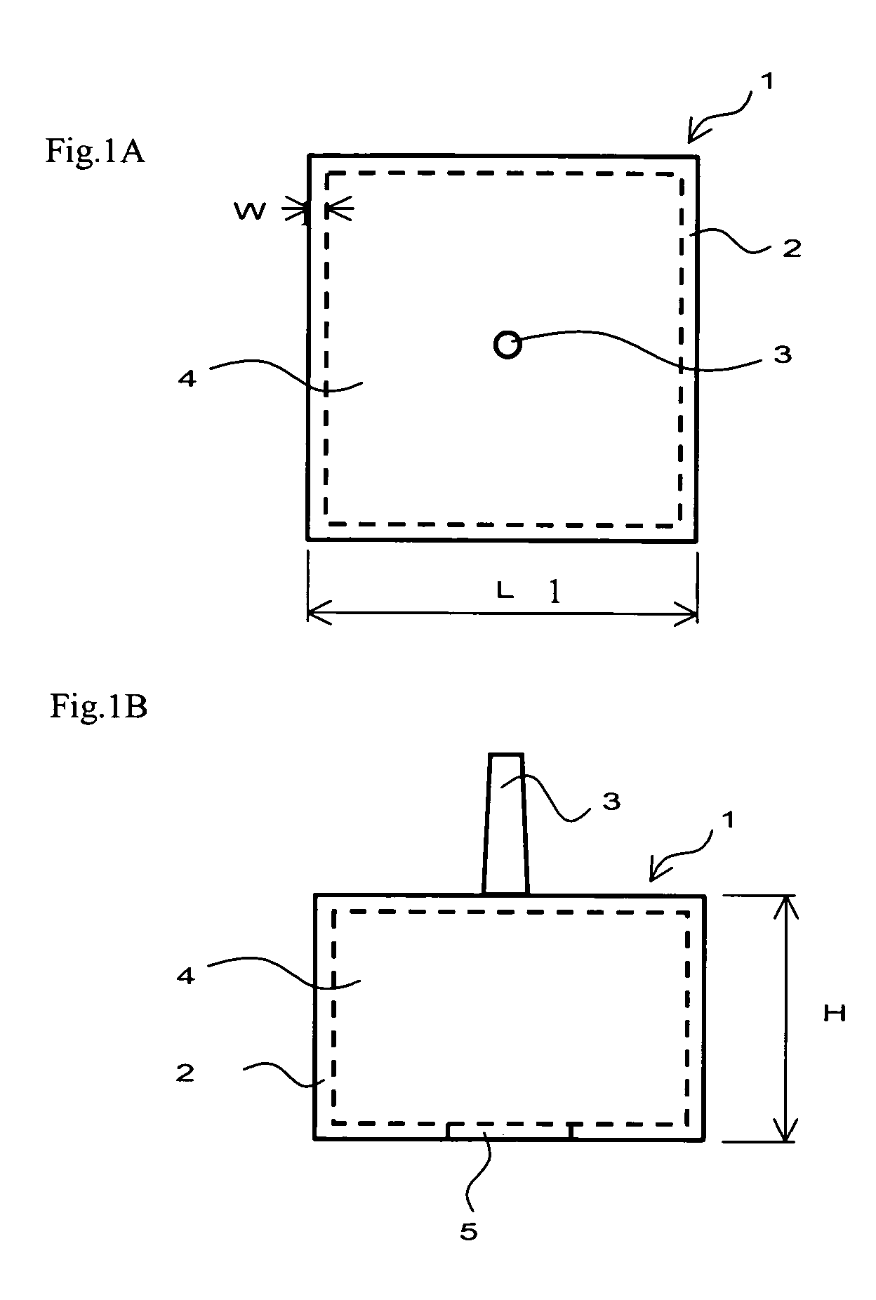
[0090] A tensile test piece (type ASTM1, thickness of 3.2 mm) was produced using an injection molding machine (Nissei 60E9ASE) under a molding condition with a cylinder temperature of 260° C. and a mold temperature of 80° C. Those accompanied by deformation of the test piece upon extruding the molding article when molded, or those with great buckling at the extruded portion were determined as unfavorable in molding, which were shown as “x” in the Table. On the other hand, those without deformation were shown as “◯” in th...

examples 1 through 10

, Comparative Examples 1 Through 12

[0107] Polybutylene terephthalate having an intrinsic viscosity of 0.81 dl / g (a-1) (“TORAYCON 100S,” manufactured by Toray Industries, Inc.) and the polybutylene terephthalate / isophthalate copolymer (PBT / I) (a-2) produced in Reference Example 1 were used to produce the ingredient (A) (polybutylene terephthalate based resin) with (a-1) alone or through blending (a-1) and (a-2). In addition, any one of the following (B-1) to (B-3) as the ingredient (B), either a mixture including the ingredients described in (C-1) to (C-9) (proportion represented by weight ratio) or a single ingredient therefrom as the ingredient (C) (organic pigment), and the following (D-1) when the ingredient (D) (glass fiber) is to be added and compounded were employed. Using a biaxial extruder with a predetermined cylinder temperature of 250° C. having a screw diameter of 57 mm, melting and kneading was carried out through feeding the ingredient (A) (polybutylene terephthalate b...

examples 11 through 22

, Comparative Examples 13 Through 21

[0121] Using a biaxial extruder with a predetermined cylinder temperature of 250° C. having a screw diameter of 57 mm, melting and kneading was carried out through feeding the ingredient (A) (polybutylene terephthalate based resin), the above-mentioned polycarbonate resin (B-1), either a mixture including ingredients described in (C-1) to (C-9) (proportion represented by weight ratio) or a single ingredient therefrom, as well as the following material as the ingredient (E) and another additive from a breech-loading part, and feeding the ingredient (D) (glass fiber) from a side feeder when it is to be added and compounded. After cooling the strand which was discharged from the die in a cooling bath, a resin composition for laser welding was obtained by pelletizing with a strand cutter. After drying the thus resulting each material with a hot air drier at 130° C. for 3 hours, molding and then evaluation were performed. The results of evaluation are ...


PUM

PropertyMeasurementUnit
thicknessaaaaaaaaaa
thicknessaaaaaaaaaa
thicknessaaaaaaaaaa

Abstract

A colored resin composition for laser welding which comprises: (A) a polybutylene terephthalate based resin comprising polybutylene terephthalate or polybutylene terephthalate and a polybutylene terephthalate copolymer, (B) at least one kind of resin selected from polycarbonate resins, styrene based resins and polyethylene terephthalate resins, and (C) two or more kinds of organic pigments, wherein the resin (B) accounts for 1 to 50% by weight of the total amount of the polybutylene terephthalate based resin (A) and the resin (B), the pigment (C) is included in an amount of 0.02 to 0.5 parts by weight per 100 parts by weight of the total amount of the polybutylene terephthalate based resin (A) and the resin (B), laser beam transmittance in the near infrared radiation region of the wavelength of 800 nm to 1100 nm is 10% or greater when it is measured with a sample thickness of 3 mm, and L value which indicates the luminosity is less than 50.

Description

BACKGROUND OF THE INVENTION [0001] The present invention relates to a resin composition for laser welding which is well-balanced and excellent in heat resistance, thermal shock property, appearance of molding article surface, dimensional stability and laser welding property, and a composite molding product using the same, and more particularly, relates to a polybutylene terephthalate based resin composition which is suitable for a composite molding product and the like obtained by laser welding to another article, and a composite molding product using the same. [0002] Polybutylene terephthalate resins have been extensively utilized as an injection molding product, in fields such as machine parts, electrical / communication parts, automobile parts and the like by employing their excellent injection moldability, mechanical characteristics, heat resistance, electrical characteristics, chemical resistance and the like. However, although efficiency of formation of the injection molding art...

Claims


Application Information

Patent Timeline
Patent Type & Authority Applications(United States)
IPC IPC(8): C08K3/00C08K3/04C08K3/10C08K3/34C08K3/38C08K3/40C08K5/00C08K5/34C08L25/04C08L67/02C08L67/03C08L69/00
CPCB29C65/1677B29C65/1609B29C65/1616B29C65/1635B29C65/1658B29C65/8215B29C66/1122B29C66/43B29C66/71B29C66/7212B29C66/7332B29C66/73921B29C66/836B29K2025/00B29K2067/00B29K2995/002C08K3/013C08K5/0041C08L25/04C08L67/02C08L69/00C08L2666/02B29K2307/04B29K2309/08B29K2277/10B29K2305/00B29K2309/02B29K2309/12B29K2067/003B29K2067/006B29K2069/00B29K2025/04B29K2009/06
Inventor ISHII, TOMOSATO, SHUNJINISHIZAWA, MASAHIRO
Owner TORAY IND INC
Why Eureka
Try Eureka