Volumetric CT system and method utilizing multiple detector panels

Inactive Publication Date: 2006-05-30
GENERAL ELECTRIC CO
View PDF5 Cites 20 Cited by
  • Summary
  • Abstract
  • Description
  • Claims
  • Application Information

AI Technical Summary

Benefits of technology

[0006]The present technique provides a means for increasing the available field of view of an imaging system while also increasing the available resolution of the imaging system. In particular, an imaging system is provided in which the detector comprises two or more flat

Problems solved by technology

However, CT detectors may not provide sufficient resolution to accurately resolve structures on the order of 0.5 to 1.5 mm, which may still be of diagnostic and pathological interest.
This lack

Method used


Image

  • Volumetric CT system and method utilizing multiple detector panels
  • Volumetric CT system and method utilizing multiple detector panels
  • Volumetric CT system and method utilizing multiple detector panels

Examples


Embodiment Construction

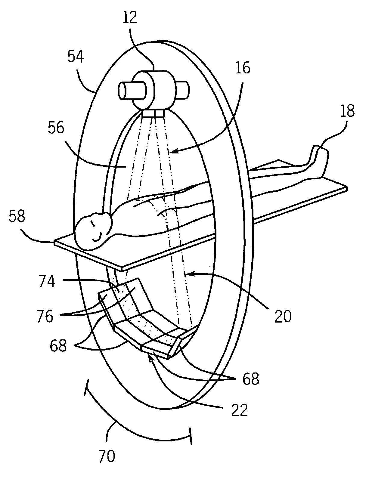
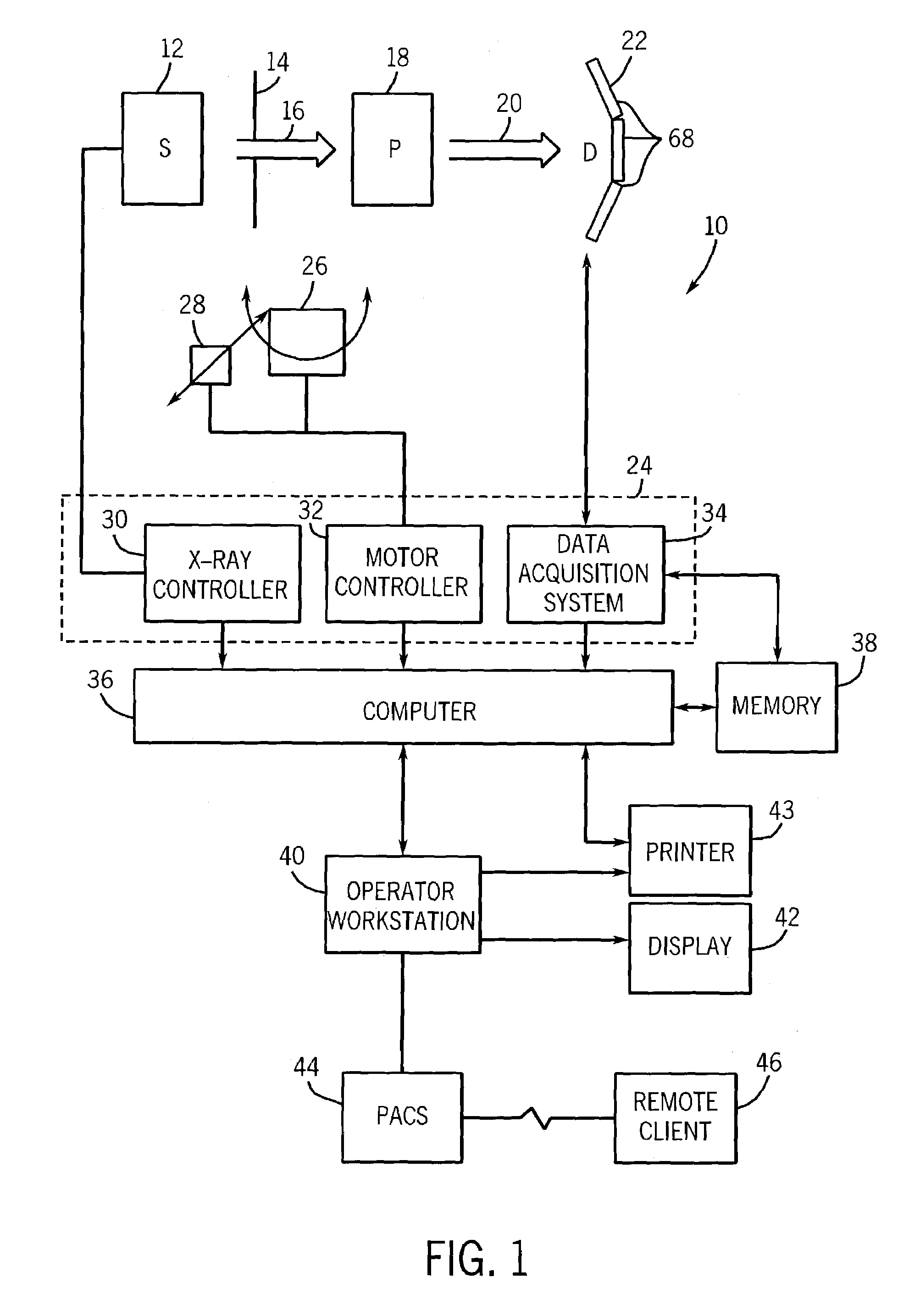
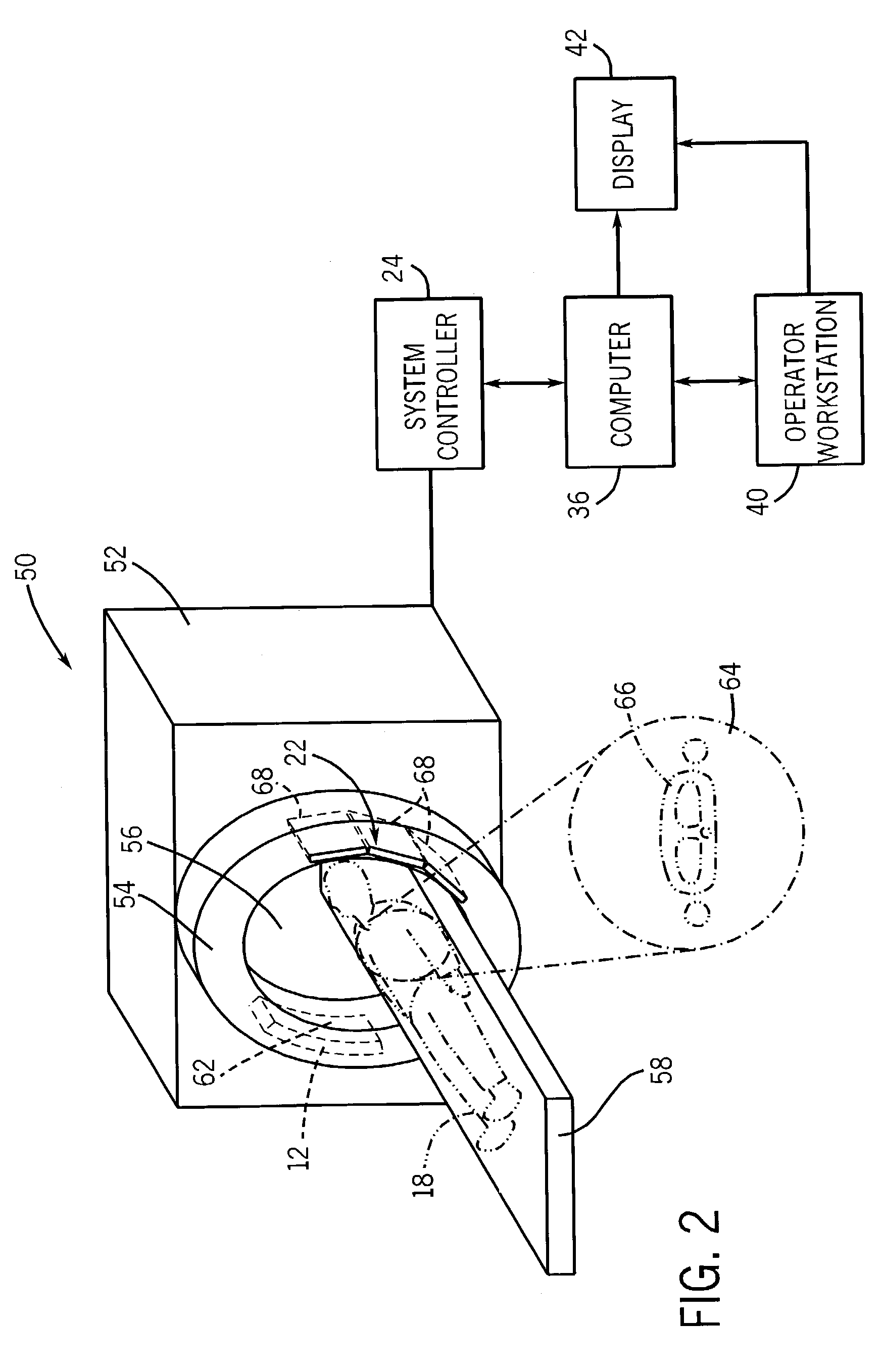
[0017]FIG. 1 illustrates diagrammatically an imaging system 10 for acquiring and processing image data. In the illustrated embodiment, system 10 is a computed tomography (CT) system designed both to acquire original image data, and to process the image data for display and analysis in accordance with the present technique. In the embodiment illustrated in FIG. 1, imaging system 10 includes a source of X-ray radiation 12 positioned adjacent to a collimator 14. In this exemplary embodiment, the source of X-ray radiation source 12 is typically an X-ray tube. Collimator 14 permits a stream of radiation 16 to pass into a region in which a subject, such as a human patient 18 is positioned.

[0018]A portion of the radiation 20 passes through or around the subject and impacts a detector, represented generally at reference numeral 22. Elements of the detector 22 produce electrical signals that represent the intensity of the incident X-ray beam. These signals are acquired and processed to recon...


PUM


Abstract

A method and apparatus for providing a configurable field of view in a non-invasive imaging system, such as a CT medical imaging system. A detector structure comprising two or more flat-panel X-ray detectors is provided such that the configurable field of view may encompass the full area of the two or more X-ray detectors or any suitable subset of the full area. The field of view may be configured based upon an acceptable field of view in conjunction with an acceptable scan speed.

Description

BACKGROUND OF THE INVENTION[0001]The present invention relates generally to the field of non-invasive imaging and, more specifically, to the field of medical imaging using Computed Tomography systems.[0002]Computed Tomography (CT) imaging systems measure the attenuation of X-ray beams passed through a patient from numerous angles. Based upon these measurements, a computer is able to reconstruct images of the portions of a patient's body responsible for the radiation attenuation. As will be appreciated by those skilled in the art, these images are based upon separate examination of a series of angularly displaced projection images. It should be pointed out that a CT system produces data that represents the line integral of linear attenuation coefficients of the scanned object. This data is then reconstructed to produce an image which is typically displayed on a cathode ray tube, and may be printed or reproduced on film. A virtual 3-D image may also be produced by a CT examination.[00...

Claims


Application Information

Patent Timeline
IPC IPC(8): A61B6/00G01T1/00A61B6/03G01N23/04G01T1/20G01T1/29G06T1/00H04N1/04H04N1/17
CPCA61B6/032A61B6/4014A61B6/469G01N23/046G01T1/2985A61B6/508A61B6/563A61B6/503G01N2223/612G01N2223/419
Inventor ROSS, WILLIAMEDIC, PETER MICHAELBASU, SAMITISHAQUE, NADEEMWALTER, DEBORAHMCLEOD, JOHN
Owner GENERAL ELECTRIC CO
Why Eureka
Try Eureka