Power control for a transmitter

a power control and transmitter technology, applied in the field of transmitters, can solve the problem of not being able to use exclusively a power control, and achieve the effect of enabling a linear power control over a larger rang

Active Publication Date: 2006-05-30
NOKIA TECHNOLOGLES OY
View PDF15 Cites 79 Cited by
  • Summary
  • Abstract
  • Description
  • Claims
  • Application Information

AI Technical Summary

Benefits of technology

[0015]It is an advantage of the invention that it enables a linear power control over a larger range, which is also efficient at the critical high power levels.
[0016]The proposed adjustment of the amplitude and/or the phase of the split up signals can be used at the same time for applying a desired amplitude modulation to the phase-modulated constant-envelope radio-frequency signal.
[0017]The proposed transmitter can be in particular, though not exclusively, an EER transmitter. It could also be a transmitter, for example, which transmits signals that are only phase modulated.
[0018]Other objects and features of the present invention will become apparen

Problems solved by technology

Therefore, it is not recommendable to use exclusively a

Method used


Image

  • Power control for a transmitter
  • Power control for a transmitter
  • Power control for a transmitter

Examples


first embodiment

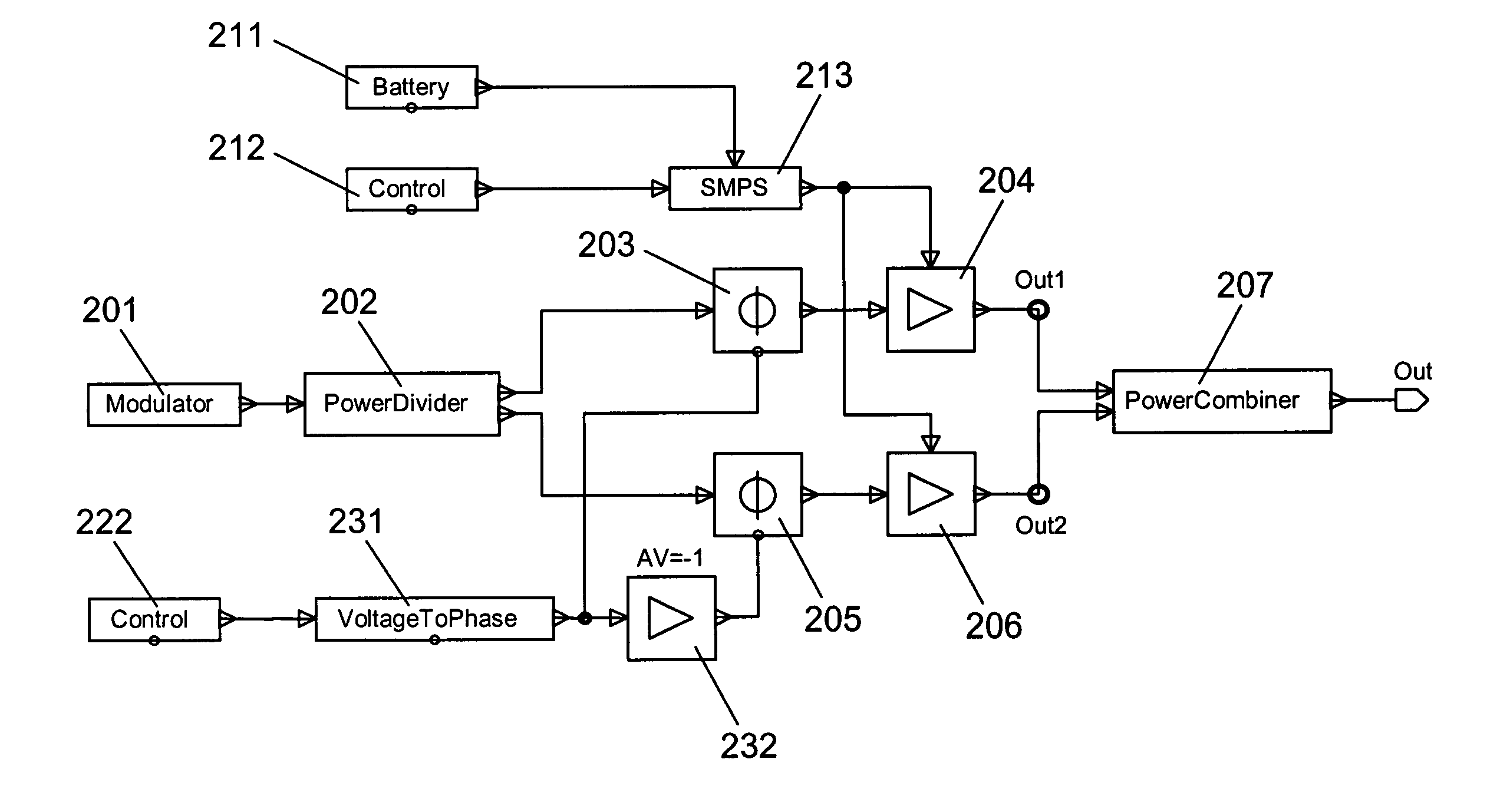
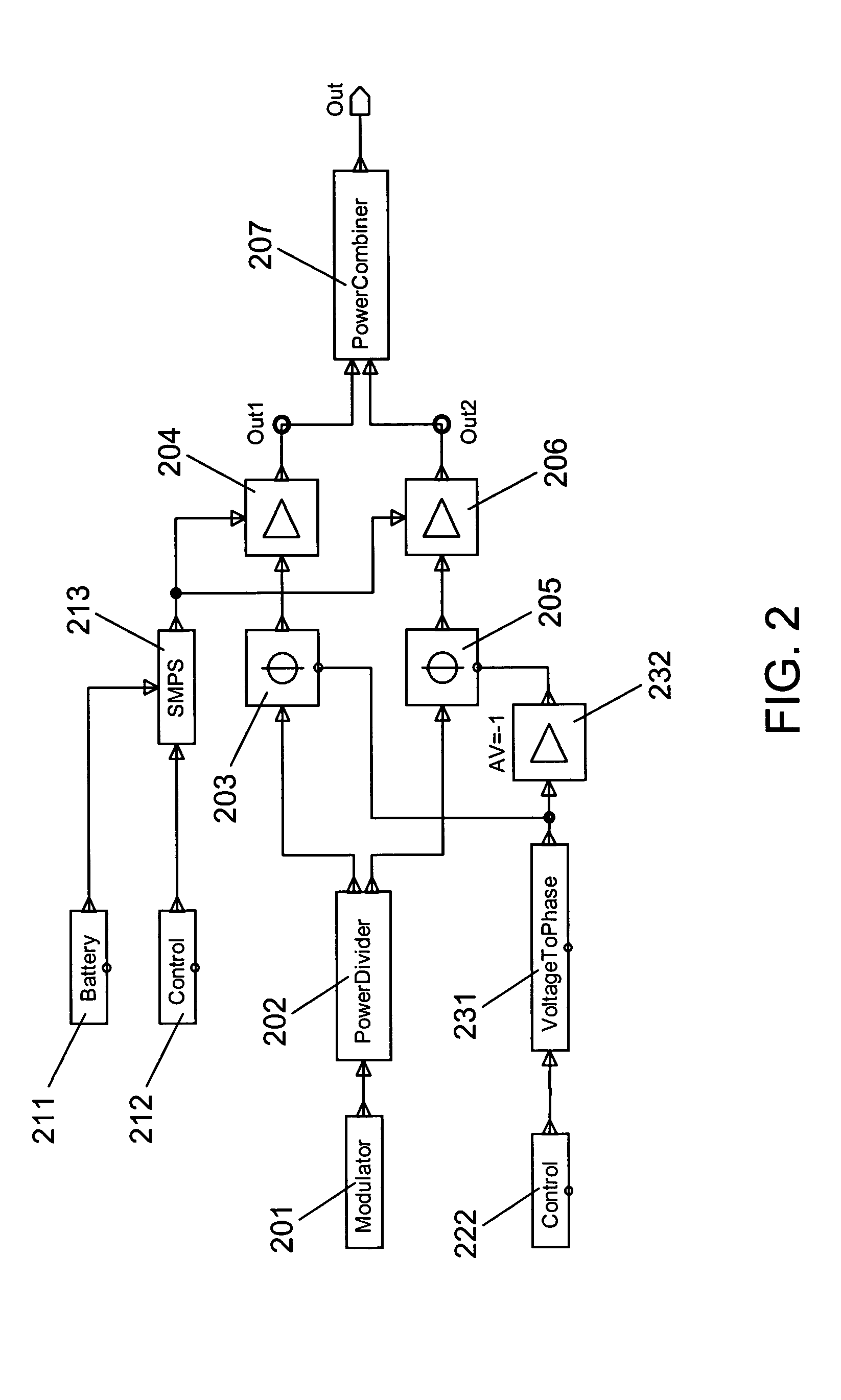
[0025]FIG. 2 is a block diagram presenting selected components of an EER transmitter according to the invention. The presented components enable an efficient power control for the EER transmitter over a large power range. The EER transmitter may be used for instance in a mobile device.

[0026]The EER transmitter of FIG. 2 comprises a modulator 201, the output of which is connected to the input of a power divider 202. A first output of the power divider 202 is connected via a first phase shifter 203 to a signal input of a first E-class power amplifier 204. A second output of the power divider 202 is connected via a second phase shifter 205 to a signal input of a second E-class power amplifier 206. The output of both power amplifiers 204, 206 is connected to a respective input of a power combiner 207, e.g. a Wilkinson power combiner.

[0027]The output of the power combiner 207 constitutes at the same time the output ‘Out’ of the EER transmitter.

[0028]The EER transmitter of FIG. 2 comprise...

third embodiment

[0056]FIGS. 4 and 5 are block diagrams presenting selected components of a second and an EER transmitter according to the invention, respectively, which additionally take care of such errors in amplitude and phase.

[0057]Like the EER transmitter of FIG. 2, the EER transmitter of FIG. 4 comprises a modulator 401, a power divider 402, a first phase shifter 403, a first E-class power amplifier 404, a second phase shifter 405, a second E-class power amplifier 406 and a power combiner 407. These components are also arranged in the same way as the corresponding components of FIG. 2.

[0058]The EER transmitter of FIG. 4 moreover again comprises a battery 411 and a first control signal generator 412, which are both connected to a respective input of an SMPS 413. Here, the output of the SMPS 413 is only connected to the control input of the first power amplifier 404, though. The EER transmitter of FIG. 4 additionally comprises a first voltage generator 414. The voltage generator 414 is connecte...


PUM


Abstract

The invention relates to a transmitter which comprises a modulator providing a phase-modulated constant-envelope radio-frequency signal, and to a method of controlling the power level of a signal output by such a transmitter. In order to enable a power control over a large power range, it is proposed that a provided phase-modulated constant-envelope radio-frequency signal is divided into two identical signals for the power control. A first control arrangement then controls the output power for higher power levels by controlling amplifications applied to the two signals. A second control arrangement controls the output power for lower power levels by controlling phase shifts applied to the two signals. The processed signals are then combined and provided as a power controlled output signal.

Description

FIELD OF THE INVENTION[0001]The invention relates to a transmitter comprising a modulator which provides a phase-modulated constant-envelope radio-frequency signal, for instance an envelope elimination and restoration (EER) transmitter. The invention relates equally to a method for realizing a power control for such a transmitter.BACKGROUND OF THE INVENTION[0002]In order to enable a transmission of phase and amplitude information of a signal via the radio interface, the signal first has to be converted into a radio-frequency signal comprising the original phase and amplitude information. For such a conversion, EER transmitters offer a better efficiency than traditional IQ-modulator architectures, which makes EER transmitters of particular interest for mobile devices. The better efficiency is achieved especially for linearly modulated signals for which the peak-to-average ratio (PAR) can be quite high.[0003]In an EER transmitter, first the envelope of the signal that is to be transmi...

Claims


Application Information

Patent Timeline
IPC IPC(8): H04B1/04H03F1/02H03F1/06H03F3/21H03F3/60
CPCH03F1/02H03F1/0205H03F3/602H03F3/211H03F1/0211H03F3/21H03F1/06
Inventor ROSNELL, SEPPO
Owner NOKIA TECHNOLOGLES OY
Why Eureka
Try Eureka