
Automatic reset signal generator integrated into chipset and chipset with reset completion indication function

a technology of automatic reset and signal generation, which is applied in the direction of pulse technique, error detection/correction, instruments, etc., can solve the problems of limited efficiency of the reset system, the cpu cannot proceed any command cycle, and the need to reboot or reset the computer system, so as to avoid undesirable interruption of mtbf tests.

Active Publication Date: 2006-05-30
VIA TECH INC
View PDF8 Cites 21 Cited by
  • Summary
  • Abstract
  • Description
  • Claims
  • Application Information

AI Technical Summary

Benefits of technology

The present invention provides a circuit for automatically resetting a central processing unit (CPU) when it unexpectedly suspends operation for a predetermined period of time. This circuit includes a detector and a reset signal generator. The detector receives a specified operation of the CPU and sends out a triggering signal when the operation is not completed for a predetermined period of time. The reset signal generator generates a reset signal in response to the triggering signal. The circuit can be integrated into a chipset and provides a reset completion indication function for the functional circuits connected to the chipset. The technical effect of this invention is to ensure continuous operation of servers or remote-controlled computers, and avoid interruptions in MTBF tests.

Problems solved by technology

In a personal computer, when hardware or software thereof operates improperly, for example resulting from an unstable power supply, or hang-up caused by a software bug, the central processing unit (CPU) will be unable to proceed any command cycle, and it is required to reboot or reset the computer system.
The efficiency of such reset system is limited, especially when employed in ceaselessly operating servers, remote-controlled computer or mean time between failure (MTBF) tests after manufactured.
There is likely to be unnecessary time waste.
In addition, such reset system is not capable of identifying whether the reset operations are complete and / or which functional circuit has not been reset.

Method used


Image

  • Automatic reset signal generator integrated into chipset and chipset with reset completion indication function
  • Automatic reset signal generator integrated into chipset and chipset with reset completion indication function
  • Automatic reset signal generator integrated into chipset and chipset with reset completion indication function

Examples


Embodiment Construction

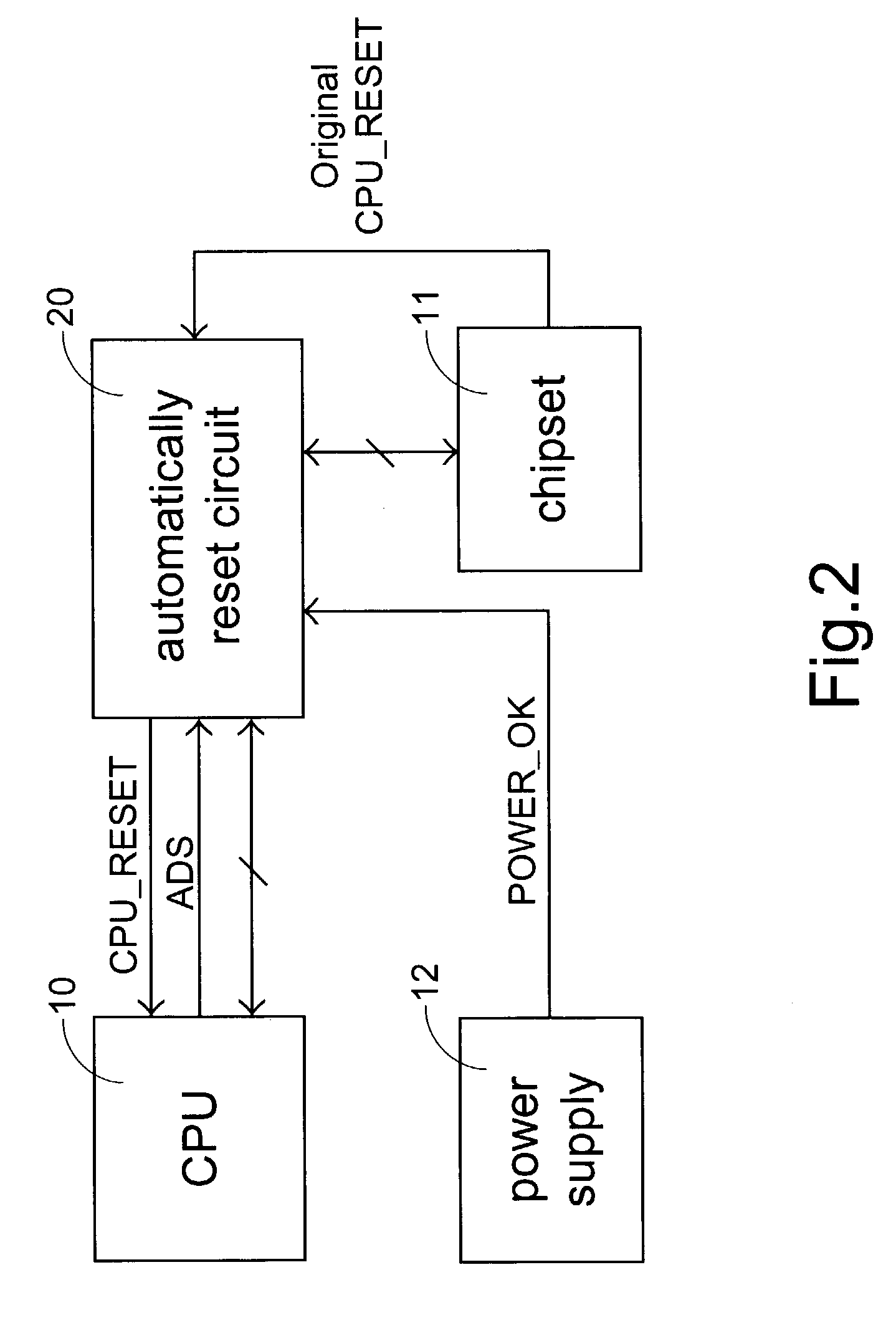
[0029]Referring to FIG. 2. The automatically reset system according to the present invention includes a central processing unit (CPU) 10, a chipset 11, a power supply 12 and further an automatically reset circuit 20. The automatically reset circuit 20 is electrically coupled to the CPU 10, the chipset 11 and the power supply 12, and will receive an address strobe signal ADS from the CPU 10 and an original reset signal Original CPU_RESET from the chipset 11 to determine if a hang-up occurs. The automatically reset circuit 20 continuously monitors the address strobe signal ADS from the CPU 10. Once the CPU 10 suspends the output of the address strobe signal ADS and thus the automatically reset circuit 20 has not received the address strobe signal for a predertermined period of time, a hang-up situation is determined happened. Therefore, a reset signal CPU_RESET is outputted by the automatically reset circuit 20 to the CPU 10 in order to activate the CPU reset procedure.

[0030]FIG. 3 il...


PUM


Abstract

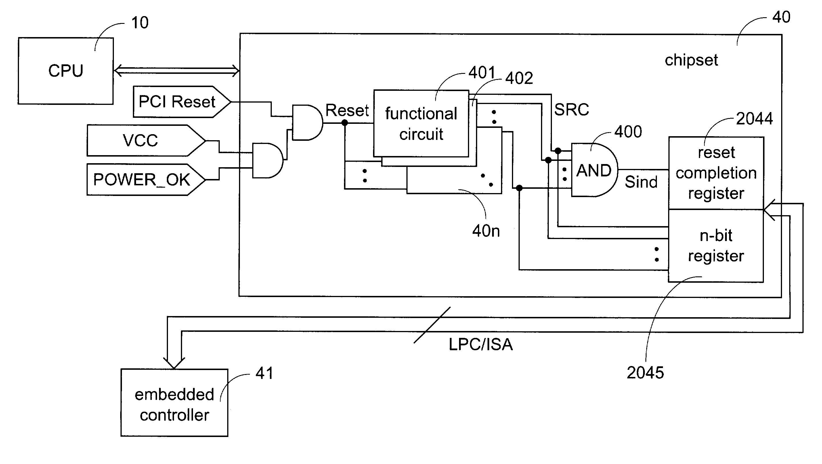
A circuit for automatically resetting a central processing unit (CPU) is provided. The circuit includes a detector and a reset signal generator. The detector is electrically connected to the CPU for receiving a specified signal from the CPU, and the detector sends out a triggering signal when the specified signal is not received for a predetermined period of time. The reset signal generator is electrically connected to the detector for generating a reset signal in response to the triggering signal. A chipset with a reset completion indication function is also provided. The chipset includes a plurality of functional circuits and a calculating and recording device.

Description

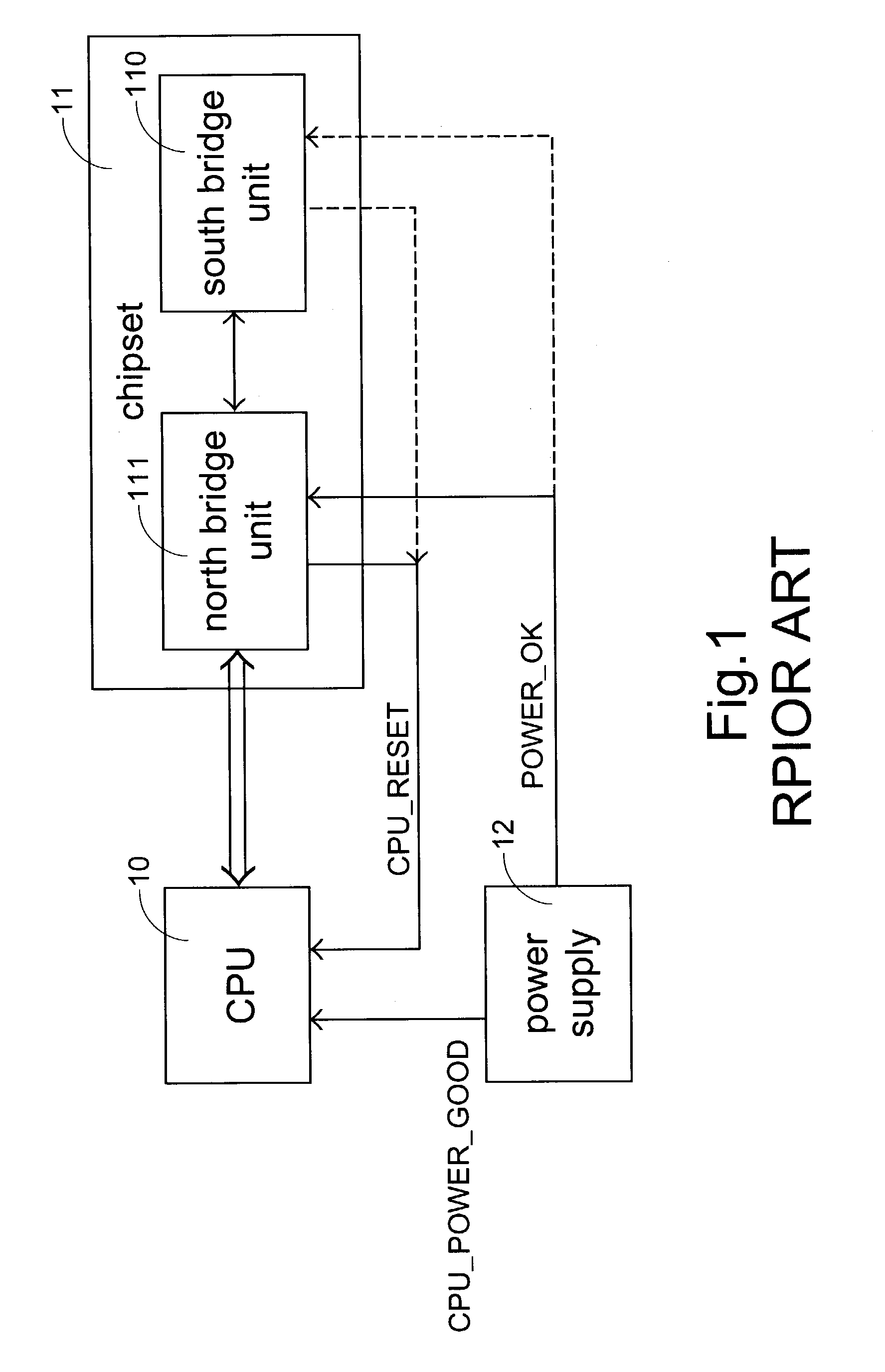
FIELD OF THE INVENTION[0001]The present invention relates to an automatically resetting circuit for a central processing unit, and more particularly to an automatically resetting circuit for a central processing unit, which is integrated into a chipset. The present invention also relates to a chipset with a reset completion indication function.BACKGROUND OF THE INVENTION[0002]In a personal computer, when hardware or software thereof operates improperly, for example resulting from an unstable power supply, or hang-up caused by a software bug, the central processing unit (CPU) will be unable to proceed any command cycle, and it is required to reboot or reset the computer system. Conventionally, the user has to utilize a hardware apparatus such as a reset button or a combination of keys Ctrl+Alt+Del to reset the CPU.[0003]Referring to FIG. 1, a typical reset configuration for a personal computer system includes a central processing unit (CPU) 10, a chipset 11 and a power supply 12. Dur...

Claims


Application Information

Patent Timeline
Patent Type & Authority Patents(United States)
IPC IPC(8): G06F11/00G06F1/24
CPCG06F1/24
Inventor LIN, SCOTT
Owner VIA TECH INC
Learn More