Spacer plate for use with internal combustion engines

a technology for internal combustion engines and spacer plates, which is applied in the direction of combustion-air/fuel-air treatment, fuel re-atomisation/homogenisation, charge feed systems, etc., can solve the problems of increasing horsepower and torque, reducing fuel consumption and exhaust emissions, and all throttle body spacer plates, so as to improve engine performance, improve gas mileage, and reduce fuel consumption

Inactive Publication Date: 2006-06-06
TAYLOR CABLE PROD
View PDF2 Cites 8 Cited by
  • Summary
  • Abstract
  • Description
  • Claims
  • Application Information

AI Technical Summary

Benefits of technology

[0018]The present invention, as described below, addresses the problems discussed above and other problems, which will become apparent to one skilled in the art. Generally, the present invention provides a spacer plate having a particular air flow passage configuration, which improves engine performance, decreases fuel consumption and provides for better gas mileage, results in more end torque, more horsepower, and other various functions that will become apparent from the description below. Generally, the present invention provides a spacer having a particular air flow passage configuration which improves engine performance, decreases fuel consumption (i.e., provides for better gas mileage), may result in more torque, easier starting, more horsepower, and other various functions which will become apparent from the description below.
[0023]As a further advantage, and unlike existing spacer plates now available, the positive attributes of the present invention do not decrease or fluctuate as engine RPM and intake air velocity increase. This invention maintains a reasonably constant frequency and flow preventing excessive degradation of the air flow characteristics. Therefore, the invention does not favor a narrow RPM operating band but, to the contrary, operates efficiently at all operational ranges and for application in any internal combustion engine, as opposed to limited applications.

Problems solved by technology

These devices alleged to decrease fuel consumption and exhaust emissions, while increasing horsepower and torque.
The main disadvantages of all throttle body spacer plates heretofore known are evident from their design.
While U.S. Pat. No. 6,338,335 issued to Patterson / Brown alleged that a top to bottom helix groove both increased the velocity of the air charge and swirled the air flow, this device failed to address current trends in internal combustion engineering.
While Patterson / Brown claimed to introduce an turbulence to the incoming air, the resulting turbulence diminished the design characteristics of the engine manufacture's intake manifold and piston / combustion chamber design.
In addition, as the air velocity increased, the device favored only the narrow low band RPM operating range, and became ineffective in the high band RPM operating range due to the lack the device's ability to generate proper and effective manipulation of the air flow.

Method used


Image

  • Spacer plate for use with internal combustion engines
  • Spacer plate for use with internal combustion engines
  • Spacer plate for use with internal combustion engines

Examples


Embodiment Construction

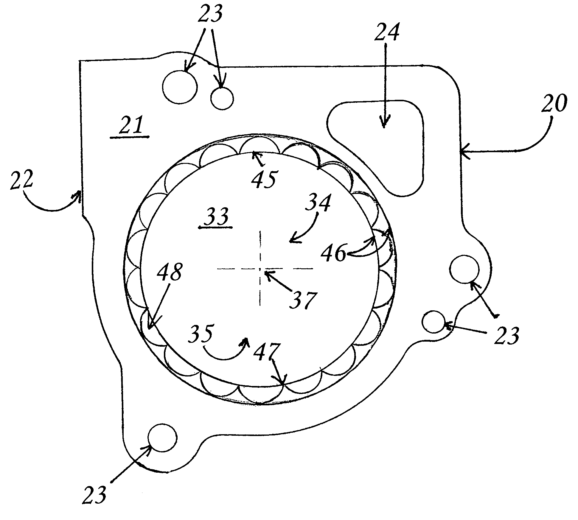
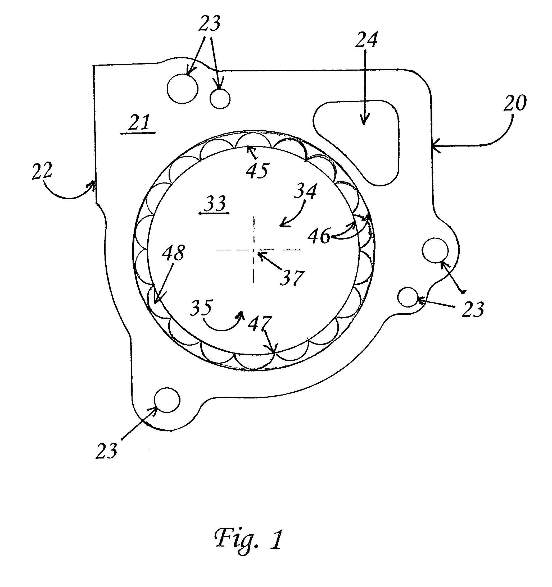
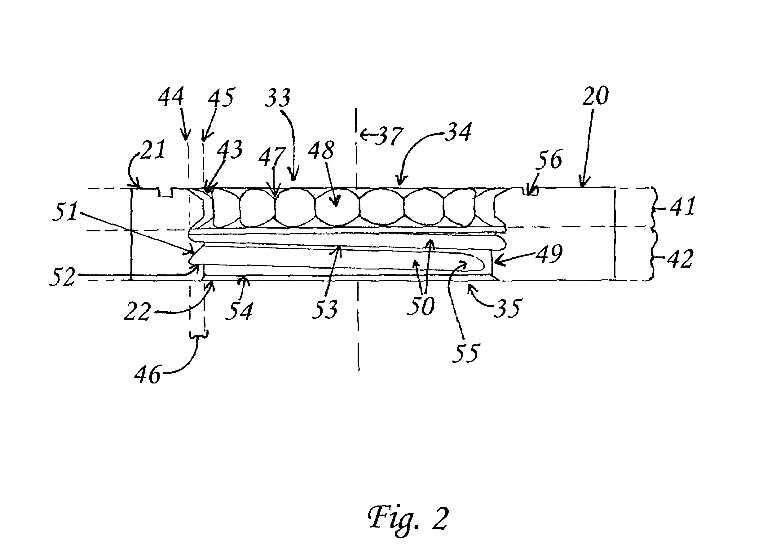
[0028]The present invention shall generally be described with reference to FIGS. 1, 2, 3a and 3b. FIG. 1 is a detailed top perspective view of a device according to the present invention. Cross-sectional views of the device are shown in FIG. 2, 3a and 3b. FIG. 2 is a detailed cross-section view of a device according to the present invention. FIG. 3a is a top cross-section perspective view and FIG. 3b is a bottom cross-section perspective view of a device according to the present invention.

[0029]One skilled in the art will recognize that the device shown in FIGS. 1, 2, 3a, and 3b may be a part of any device (e.g. spacer, adaptor, riser, etc) for use with the intake path in any internal combustion engine. For example, such devices may be utilized in an intake path used with either a carburetor, throttle body injectors, or direct injectors in various applications such as trucks, automobiles, tractors, etc. As will become apparent from the description below, the present invention is not...


PUM


Abstract

A device for use in an air intake path of an internal combustion engine to improve the engine performance. The device body has a top surface, bottom surface and at least one air passage defined about an axis from the top surface-to the bottom surface, containing a chamfer at each end. The upper portion of the passage surface contains a plurality of V-shaped veins about the axis of the passage. The lower portion of the passage narrows in diameter to a point equal to or greater than the vein extension in the upper portion. The lower portion also defines a grooved surface starting at it's beginning having a 60 degree slope edge and a flat bottom major diameter spaced in such a manner as to have a helical shape and to circumscribe the passage wall terminating prior to the end of the lower passage.

Description

CROSS REFERENCE TO RELATED APPLICATIONS[0001]Not applicableSTATEMENT REGARDING FEDERALLY SPONSORED RESEARCH OR DEVELOPMENT[0002]Not applicableREFERENCE TO SEQUENCE LISTING, A TABLE, OR A COMPUTER PROGRAM LISTING COMPACT DISK APPENDIX[0003]Not applicableFIELD OF INVENTION[0004]This invention relates to a throttle body spacer plate for any and all internal combustion engines, specifically an incorporation of specially designed structures located within the air passage(s) of the device, that improves internal combustion engine performance with increased gas mileage, lower fuel emissions, increased horse power and torque.BACKGROUND OF THE INVENTION[0005]The use of various devices for after market insertion into the intake path of internal combustion engines is well know in the prior art. Such devices are alleged to increase fuel economy, improve torque and pulling power of a vehicle, improve throttle response, improve fuel atomization resulting in greater combustion efficiency, etc.[000...

Claims


Application Information

Patent Timeline
Patent Type & Authority Patents(United States)
IPC IPC(8): F02M29/00
CPCF02M29/14F02M29/06
Inventor BOVEIA, JOHN
Owner TAYLOR CABLE PROD
Why Eureka
Try Eureka