Grinding method of a workpiece and grinding apparatus

a technology of grinding apparatus and workpiece, which is applied in the direction of grinding drives, other manufacturing equipment/tools, manufacturing tools, etc., can solve the problems and achieve the effect of shortened grinding time and shortened setup tim

Inactive Publication Date: 2006-06-06
OKAMOTO MACHINE TOOL WORKS LTD
View PDF2 Cites 11 Cited by
  • Summary
  • Abstract
  • Description
  • Claims
  • Application Information

AI Technical Summary

Benefits of technology

[0014]One object of the present invention is to provide a grinding apparatus in which a vibration sensor is used, and a work table can be reversed at a distance where the work table moved by 20 to 75 mm from a position where a grinding wheel separates from a workpiece. Thus, the total reciprocating movement distance of the work table during grinding can be shortened.
[0017]When an irregular shaped workpiece of an L shape, a disk shape or the like is machined, in the conventional method, the work table movement is reversed by using the dogs, and the table reverse position must be inputted to the NC control device from the operation panel. Since the table reverse position is determined, as shown in FIG. 3A, there is movement of the work table in an idle (over run) portion where grinding is not performed. On the other hand, in the table reversing method using the vibration sensor according to the invention, a trace or stroke of the work table motion along the workpiece shape becomes possible, and as shown in FIG. 3B, the movement distance of the work table of the idle (over run) portion where grinding is not performed becomes very short. It is decreased by approximately 10 to 38% as compared with the conventional table reversing method using the dogs. Thus, grinding time is shortened, and it becomes unnecessary to input the table reverse position to the NC control device from the operation panel. Accordingly, setup-time is also shortened.

Problems solved by technology

Thus, grinding time is shortened, and it becomes unnecessary to input the table reverse position to the NC control device from the operation panel.

Method used


Image

  • Grinding method of a workpiece and grinding apparatus
  • Grinding method of a workpiece and grinding apparatus
  • Grinding method of a workpiece and grinding apparatus

Examples


Embodiment Construction

[0025]Hereinafter, the invention will be described in more detail with reference to the drawings.

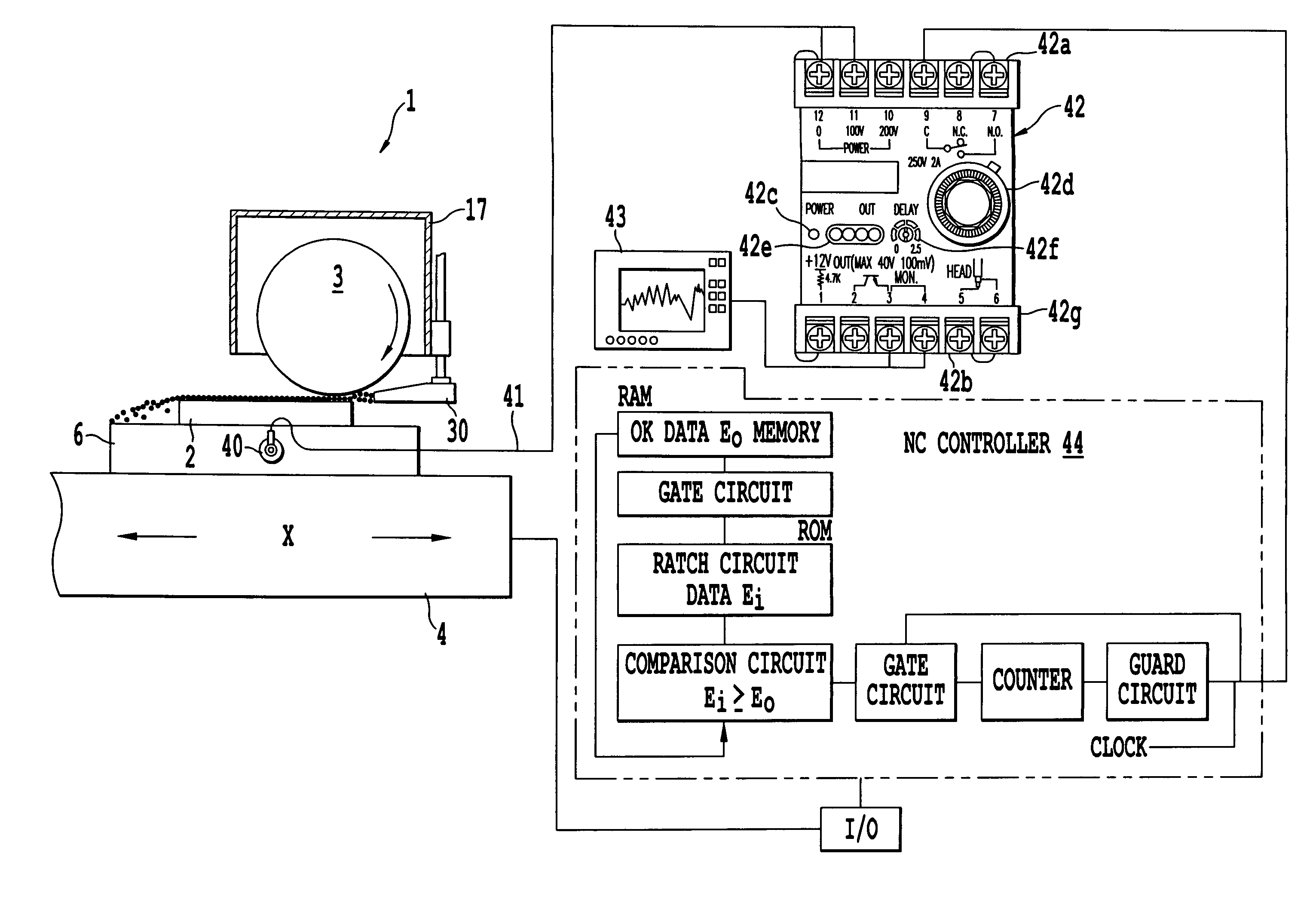
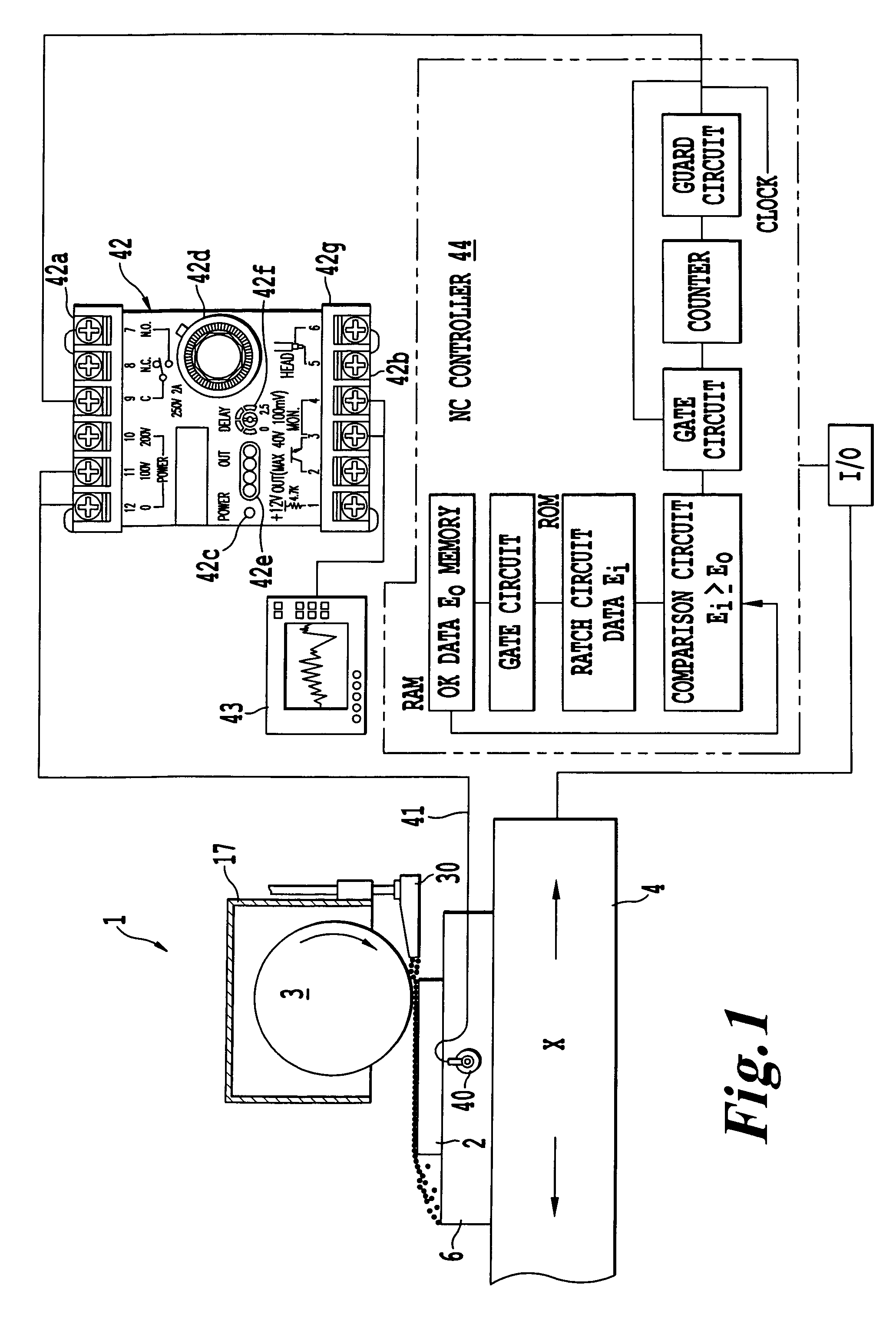
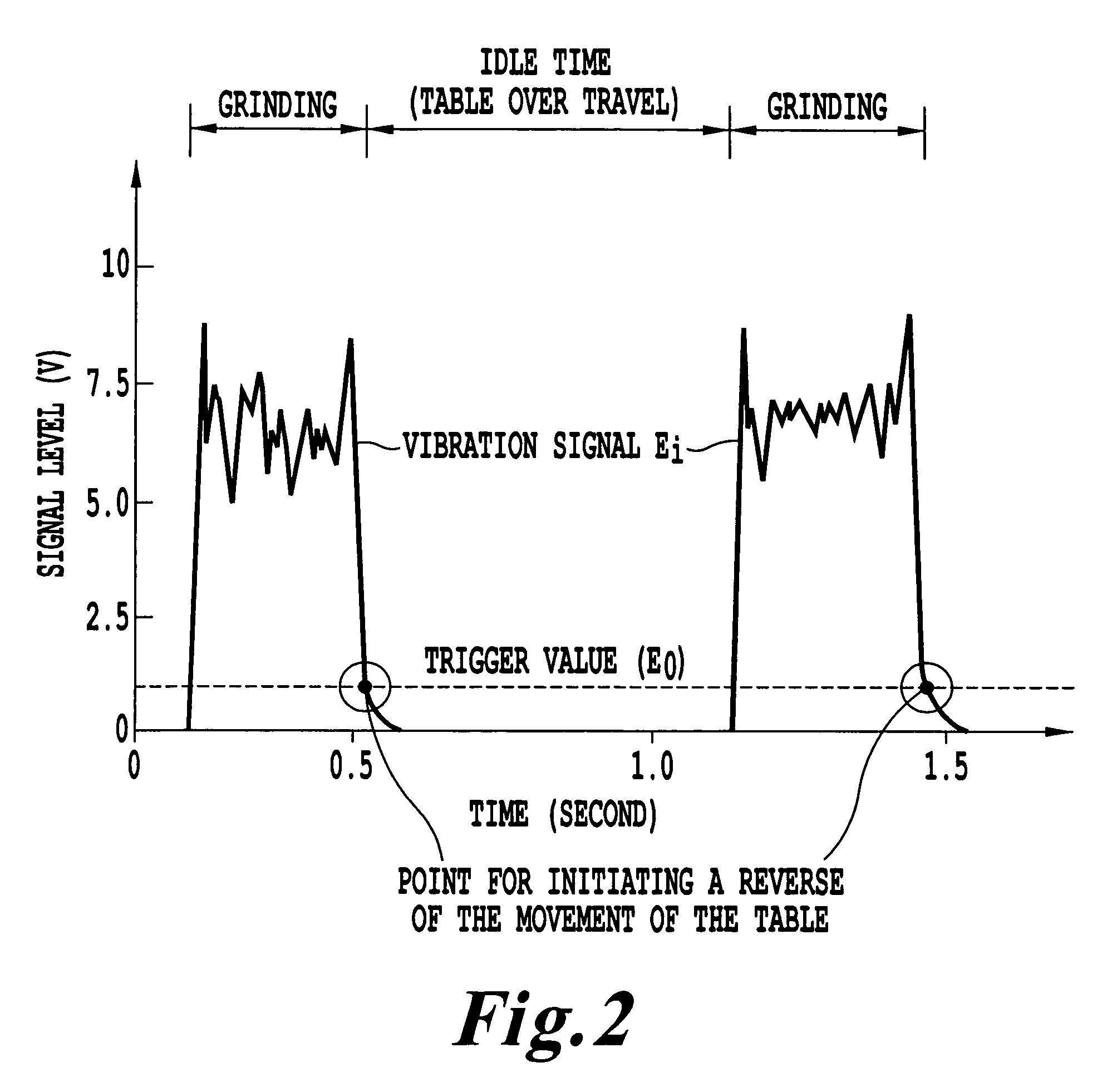
[0026]FIG. 1 is a front view of a grinding apparatus of one non-limiting embodiment of the invention including a vibration (an acoustic energy) sensor to instruct a reverse position of a work table. FIG. 2 shows a measurement example of a vibration output signal waveform when traverse grinding is performed. FIG. 3A shows a relative movement distance of a grinding wheel to an L-shaped work when a conventional grinding method is used. FIG. 3B shows a relative movement distance of a grinding wheel to an L-shaped work in a work table reversing method of the invention.

[0027]In FIG. 1, a surface grinding apparatus 1 has a workpiece 2, a grinding wheel 3, a work table 4, an electromagnetic chuck 6, a grinding wheel protective cover 17, a grinding liquid supply nozzle 30, an AE sensor head 40, a lead wire 41, a monitor voltage output device 42, a vibration data display 43 and an NC control devic...


PUM

PropertyMeasurementUnit
cutoff frequencyaaaaaaaaaa
widthaaaaaaaaaa

Abstract

An adaptive work table-reciprocation control system and method that can reduce a grinding time. The system uses a vibration sensor head installed on a chuck surface in the vicinity of the workpiece to detect a vibration signal emitted from the contact zone between the grinding wheel and the workpiece. When the value of the vibration signals falls below a trigger level, a work table direction of motion is reversed.

Description

BACKGROUND OF THE INVENTION[0001]1. Field of the Invention[0002]The present invention relates to a grinding method in which an acoustic energy sensor detects a vibration signal emitted from the contact zone between a grinding wheel and a workpiece during grinding. Movement of a work table, during grinding of the workpiece, is reversed based on the change of the vibration signal. Another non-limiting embodiment of the present invention relates to a grinding apparatus for grinding a workpiece mounted on a work table which is reversed based on the change of a time-series vibration signal detected by the acoustic energy sensor.[0003]According to the grinding method of the invention, since the reverse position of the work table is determined by the vibration signal generated by the acoustic energy (vibration) sensor according to the contour of the workpiece during grinding, when the workpiece has a shape such as a disk, a star shape, an L shape, an ellipse, a semicircle or a long shape, ...

Claims


Application Information

Patent Timeline
Patent Type & Authority Patents(United States)
IPC IPC(8): B24B49/00B24B7/02B24B47/02B24B49/10
CPCB23Q17/12B24B41/007B24B7/02
Inventor YUI, AKINORIOKUYAMA, SHIGEKIISONO, JUNICHI
Owner OKAMOTO MACHINE TOOL WORKS LTD
Why Eureka
Try Eureka