
Emission treatment system

a technology of emission treatment system and treatment system, which is applied in the direction of separation process, machine/engine, synthetic resin layered product, etc., to achieve the effect of removing additional pollutants and minimal impact on the operation of the plan

Active Publication Date: 2006-06-06
GENERAL ELECTRIC TECH GMBH
View PDF11 Cites 8 Cited by
  • Summary
  • Abstract
  • Description
  • Claims
  • Application Information

AI Technical Summary

Benefits of technology

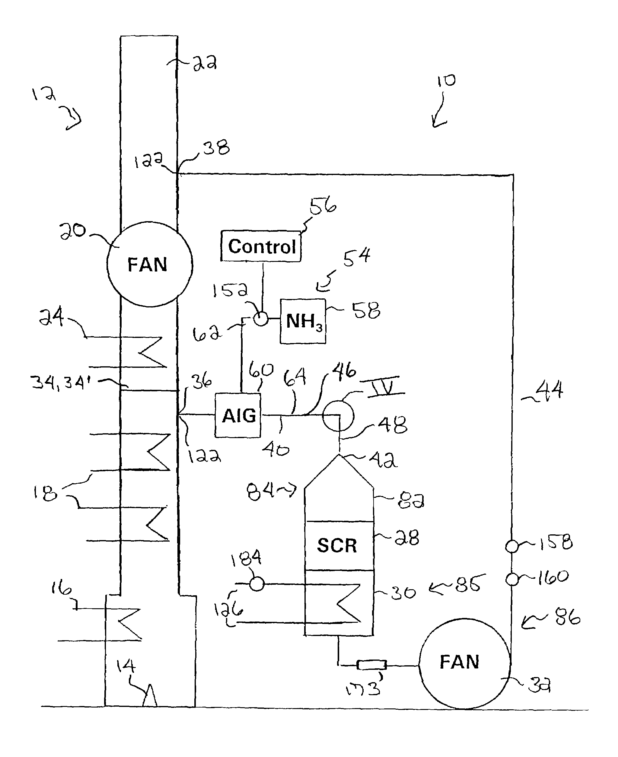
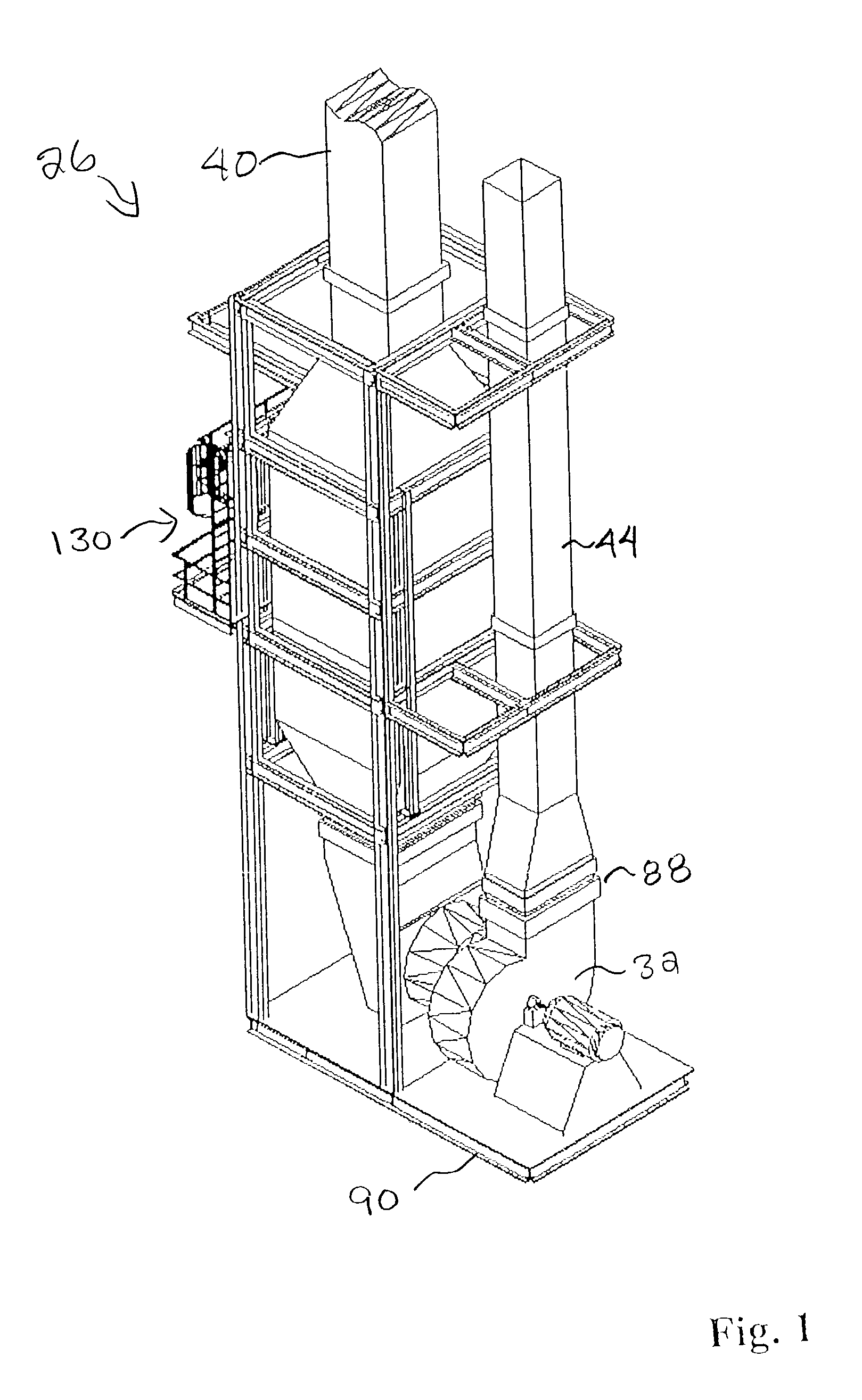
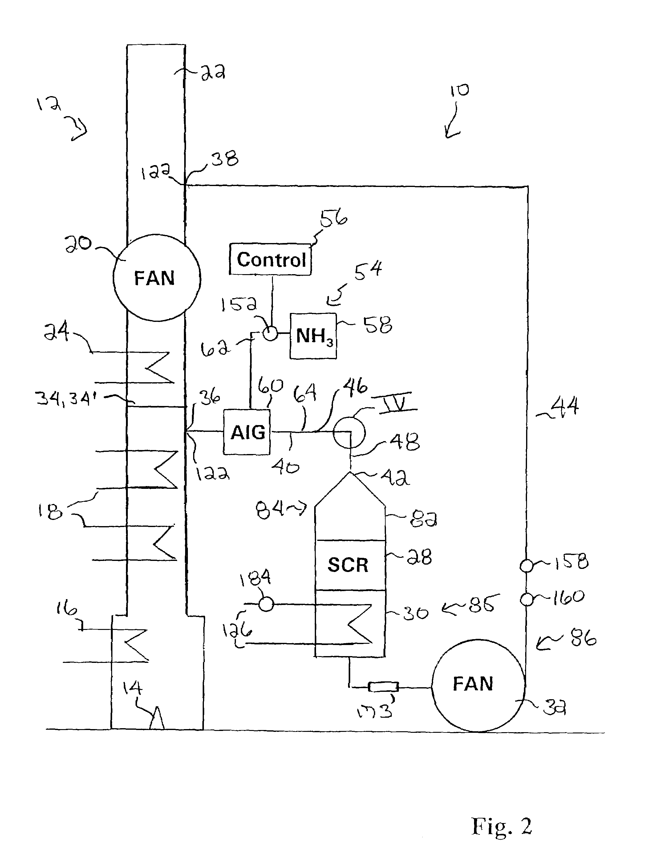
[0011]The diversion member may be either a fixed a blanking member or a moveable bypass flapper. The inlet ductwork includes a horizontal run connected to a vertical run by an elbow. At least one moveable vane may be disposed in the elbow to reduce the pressure drop therethrough.

Problems solved by technology

If the ammonia injection grid is positioned within ten feet of the stack, a mixer or diffuser is not required to ensure sufficient mixing of the ammonia vapor and flue gas.

Method used


Image

  • Emission treatment system
  • Emission treatment system
  • Emission treatment system

Examples


Embodiment Construction

[0033]As concern for the environment grows, greater efforts are being undertaken to reduce emissions of known pollutants, such as particulate matter, NOx, SOx, mercury, etc, by the promulgation of more stringent control requirements. For the refinery and petrochemical industries, the first of these more stringent requirements focuses on NOx reduction.

[0034]With reference to the drawings wherein like numerals represent like parts throughout the several figures, an emission treatment system 10 in accordance with the present invention reduces NOx by SCR technology, provides for future emissions control of other pollutants, and is a stand-alone system that may be installed on the ground along side the existing equipment, or on legs along side the existing equipment, or on top of the existing equipment, thereby reducing the downtime of the refinery or petrochemical production equipment.

[0035]The emission treatment system 10 may be utilized with most refinery and petrochemical production ...


PUM

PropertyMeasurementUnit
temperatureaaaaaaaaaa
lengthaaaaaaaaaa
sizeaaaaaaaaaa

Abstract

An emission treatment system for removing NOx from flue gas includes a diversion member that closes the stack at a position intermediate the inlet and outlet ends. A major component module includes a first sub-module, having an inlet and an SCR segment, a second sub-module, having a heat exchange segment, and a third sub-module, having an ID fan and an outlet, forming a flue gas flow path extending from the inlet to the outlet. Inlet ductwork, which is in fluid communication with the stack at a position intermediate the inlet end of the stack and the diversion member, provides a passageway from the stack to the inlet. Outlet ductwork, which is in fluid communication with the stack at a position intermediate the diversion member and the outlet end of the stack, provides a passageway from the outlet to the stack. An ammonia addition subsystem injects ammonia vapor into the inlet ductwork.

Description

BACKGROUND OF THE INVENTION[0001]This invention relates generally to processes and apparatus for the removal of nitrogen oxides or “NOx” (principally nitric oxide (NO) and nitrogen dioxide (NO2)) from exhaust gases and the like. More particularly, the present invention relates to processes and apparatus for reducing NOx selectively from exhaust gases produced during petroleum refining, petrochemical production and also to industrial processes producing exhaust gases containing NOx.[0002]Carbonaceous fuels are burned in internal combustion engines and in a wide variety of industrial process (i.e. boilers, furnaces, heaters and incinerators, petroleum refining, petrochemical production, and the like).[0003]Excess air frequently is used to complete the oxidation of combustion byproducts such as carbon monoxide (CO), hydrocarbons and soot. Free radicals of nitrogen (N2) and oxygen (O2) combine chemically to form NOx, primarily NO, at high combustion temperatures. This thermal NOx tends ...

Claims


Application Information

Patent Timeline
Patent Type & Authority Patents(United States)
IPC IPC(8): B32B27/02B01D53/86
CPCB01D53/8631B01D53/56B01D53/86
Inventor RINI, MICHAEL J.JIAN, MOURAINES, THOMAS S.AUMAUGHER, MARIE L.KUCK, NOEL C.PETIG, ARLYN V.ANDERSON, DAVID K.KOZAK, FREDERICCOCHRAN, KERI N.YANN, JAMES A.LILLESTOLEN, TOM C.HILTON, ROBERT G.
Owner GENERAL ELECTRIC TECH GMBH
Learn More