
Lineariser

a lineariser and linear technology, applied in the field of linearisers, can solve the problems of increasing the spectral space occupied by power amplifiers, introducing phase and amplitude errors in power amplifier circuitry, and increasing the power consumption of power amplifiers, so as to increase the gain and increase the signal level

Inactive Publication Date: 2006-06-06
NAGANOKEN +2
View PDF4 Cites 23 Cited by
  • Summary
  • Abstract
  • Description
  • Claims
  • Application Information

AI Technical Summary

Benefits of technology

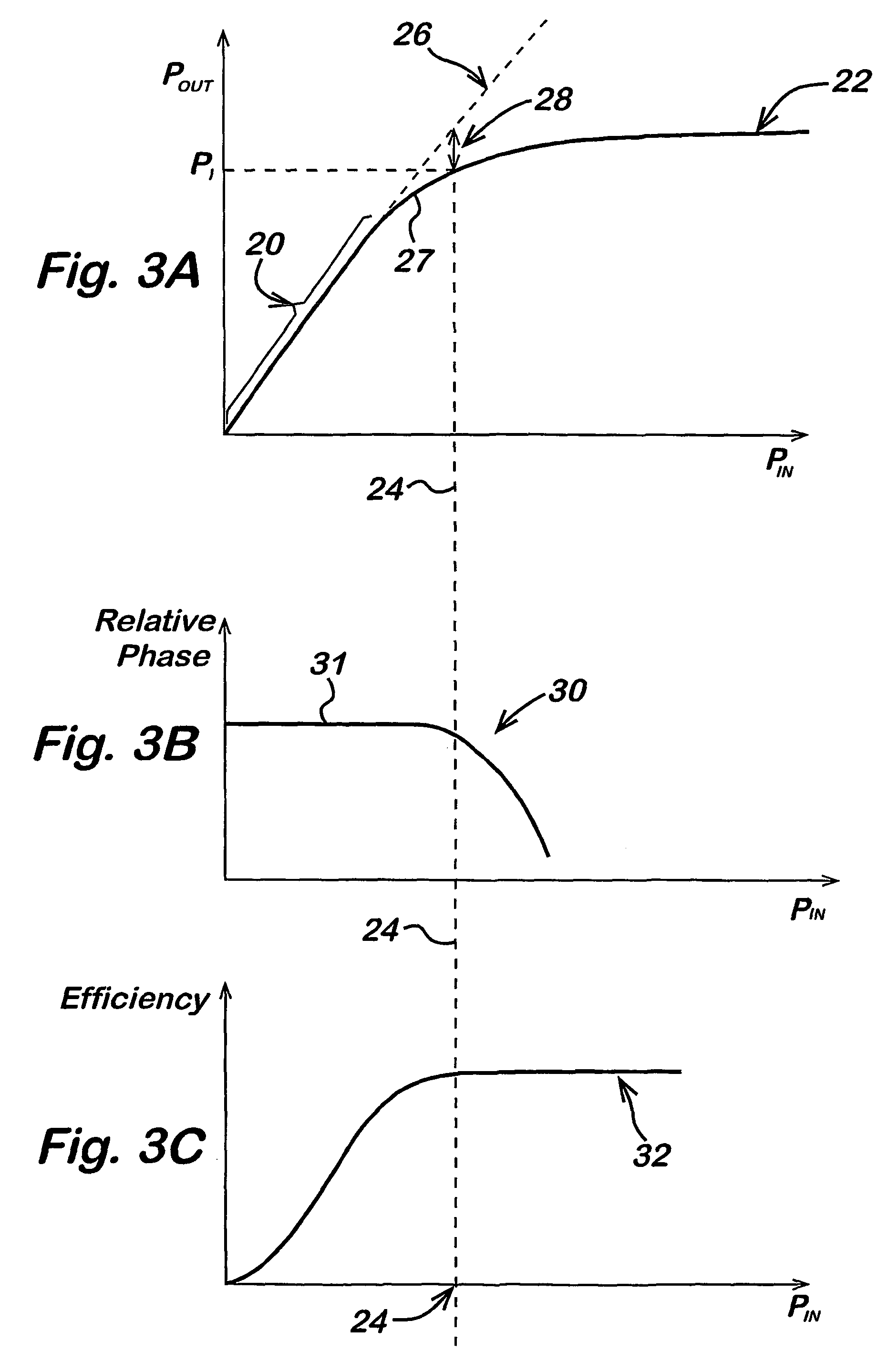
The solution reduces intermodulation distortion while maintaining amplifier efficiency, allowing operation closer to the P1 point, thus increasing the linear range of the power amplifier and reducing the need for oversized components and cooling, making it suitable for small devices.

Problems solved by technology

Power amplifier circuitry may introduce such phase and amplitude errors.
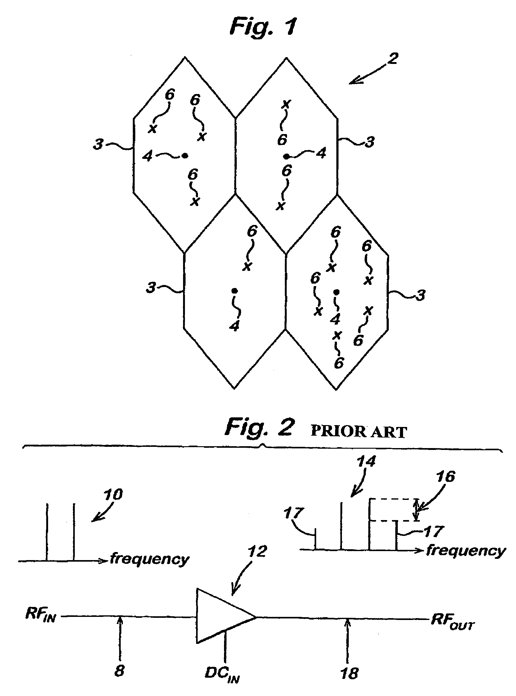
These intermodulation distortion products 17 increase the spectral space occupied and are therefore undesirable.
The power amplifier consumes more power and the size and cost of the power amplifier is increased.
Furthermore there will be increased heat dissipated by the power amplifier which may require extra cooling elements.
This all makes the use of known linearisers difficult within small low power devices.

Method used


Image

  • Lineariser
  • Lineariser
  • Lineariser

Examples


Embodiment Construction

[0030]Reference is now made to FIG. 1 which shows part of a cellular telecommunications network 2 in which embodiments of the present invention can be implemented. The area covered by the network is divided into a plurality of cells 3, four of which are shown in FIG. 1. Each cell 3 has associated therewith a base station transceiver station 4. The base transceiver stations 4 are arranged to communicate with mobile terminals 6 located in the cell associated with a given base station.

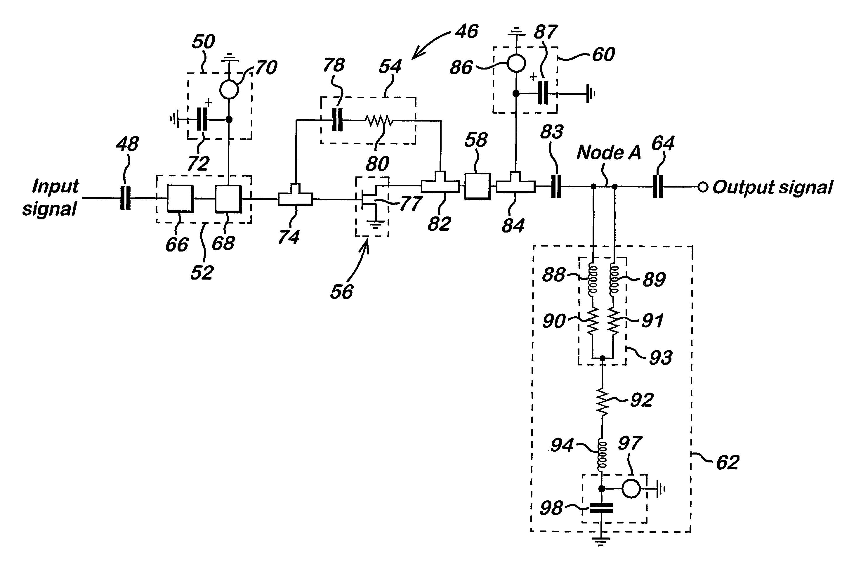
[0031]Reference is now made to FIG. 5 which shows a lineariser embodying the present invention. This lineariser may be incorporated into a mobile station or a base station. The input signal supplied by, in this case an EDGE modulator, is fed into an input decoupling capacitor 48. As the EDGE modulator is known, it will not be discussed in any more detail hereinafter. The input signal may be at a radio or intermediate frequency. The input decoupling capacitor means 48 substantially reduces any direct curre...


PUM


Abstract

The present invention relates to a lineariser for use with an amplifier. The lineariser comprises an input means and an output means. Input matching means are provided to receive an input signal. A transistor is provided, said transistor being arranged to operate substantially close to a switched on condition. The transistor is arranged to apply a non-linear gain to said input signal. The output means output the non-linear gain signal to said amplifier. The lineariser may be used with a RF power amplifier. The lineariser may be used in elements of a communication system.

Description

FIELD OF INVENTION[0001]The present invention relates to a lineariser and in particular but not exclusively to a lineariser for use with a power amplifier. The lineariser may be used in elements of a communication system.BACKGROUND OF THE INVENTION[0002]An area covered by a cellular telecommunications network is divided into a plurality of cells. Each of these cells has a base station arranged to transmit signals to and receive signals from mobile stations located in the cell associated with the respective base station. Mobile stations will be in active communication with the base station associated with the cell in which the mobile station is located.[0003]A modulation system has been developed for use within a cellular network using the Global System for Mobile communication (GSM) standard which enhances the rate at which data is transferred between the mobile stations and the base stations. This modulation scheme is called Enhanced Data rate for GSM Evolution or EDGE modulation. ...

Claims


Application Information

Patent Timeline
Patent Type & Authority Patents(United States)
IPC IPC(8): H03F3/04H03F1/32H03F3/60
CPCH03F3/602H03F1/3205
Inventor BHARJ, JASPAL
Owner NAGANOKEN
Learn More