Antenna device

a technology of antenna device and antenna earthing, which is applied in the direction of resonant antennas, substantially flat resonant elements, antenna earthings, etc., can solve the problems of device design restriction and double the cost of antenna device, and achieve the effect of reducing interference of high-frequency signals from the other feeding por

Inactive Publication Date: 2006-06-06
PANASONIC CORP
View PDF17 Cites 182 Cited by
  • Summary
  • Abstract
  • Description
  • Claims
  • Application Information

AI Technical Summary

Benefits of technology

[0011]In an embodiment of the present invention, the antenna device includes:
[0010]A conventional antenna device requires two antennas, but the antenna device of the present invention requires only one antenna. Therefore, required space for antenna installation can be reduced in half in the housing of the present antenna device, so that the housing can be downsized and the cost can be reduced.
[0027]In an antenna device of still another embodiment, the electromagnetic medium has a multilayered structure, and an impedance-matching circuit is disposed on a surface of at least one layer. Thus, an external matching circuit need not to be connected, so that a mounting area can be reduced and the cost can be reduced.

Problems solved by technology

Further, two positions for mounting the antennas need to be secured in case that two separated antennas 101 and 102 are employed, so that device design is restricted and cost required for the antenna device doubles.

Method used


Image

  • Antenna device
  • Antenna device
  • Antenna device

Examples


exemplary embodiment 1

[0065](Exemplary Embodiment 1)

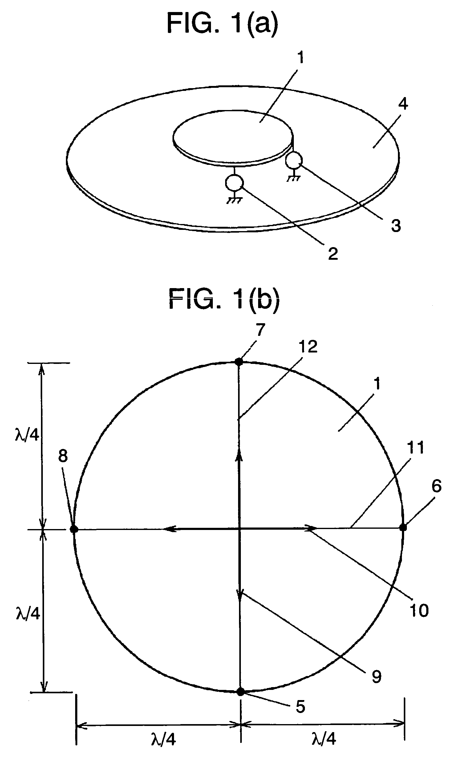
[0066]FIG. 1 (a) and FIG. 1 (b) show an antenna device in accordance with exemplary embodiment 1 of the present invention. As shown in the perspective view of FIG. 1 (a), the antenna device includes a plurality of feeding ports 2 and 3 disposed on the peripheral part of radiating plate 1 faced to ground plate 4. The shape of radiating plate 1 is a circle whose diameter is a half wavelength in electrical length at a predetermined frequency as shown in FIG. 1 (b), first feeding port 2 is disposed at one of feeding points 5 and 7, and second feeding port 3 is disposed at one of feeding points 6 and 8.

[0067]In FIG. 1 (a) and FIG. 1 (b), first feeding port 2 is connected to feeding point 5. When a signal with a predetermined frequency comes through feeding port 2, radiating plate 1 and ground plate 4 operate as a half wavelength resonator with both ends opened extending from feeding point 5 to feeding point 7, first resonance current 9 flows on radiating pla...

exemplary embodiment 2

[0072](Exemplary Embodiment 2)

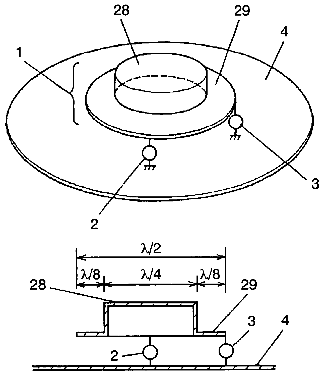
[0073]FIG. 2 shows an antenna device in accordance with exemplary embodiment 2 of the present invention. Feeding points of the previous embodiment are disposed on the outer periphery of radiating plate 1 in the antenna device shown in FIG. 1 (b). However, feeding points of this embodiment are disposed at positions having a suitable distance inwardly away from the outer periphery of radiating plate 1 in the antenna device shown in FIG. 2. The structure of FIG. 2 produces an effect of facilitating impedance-matching at each feeding point. The feeding points are disposed on first line segment 11 and second line segment 12 where the high-frequency voltage is zero, and then secure the isolation between the feeding ports.

[0074]Feeding point 27 is disposed at the center point of radiating plate 1, and a third feeding port is joined to feeding point 27. Respective signals of a predetermined frequency coming into radiating plate 1 through feeding points 5 and 6 ...

exemplary embodiment 3

[0076](Exemplary Embodiment 3)

[0077]FIG. 3 (a) and FIG. 3 (b) show antenna devices in accordance with exemplary embodiment 3 of the present invention. Radiating plate 1 of embodiment 3 is square. FIG. 3 (a) shows the case that the edge length of radiating plate 1 is a half wavelength and respective feeding points 5 and 6 connected to the first and second feeding ports are disposed on the line segments that pass through the center point of the square and are parallel with the edges. FIG. 3 (b) shows the case that the diagonal length of radiating plate 1 is a half wavelength and respective feeding points 5 and 6 connected to the first and second feeding ports are disposed on the diagonal lines of the square. In either of these cases, the third feeding port is connected to feeding point 27 at the center point of radiating plate 1. The antenna devices of the present embodiment produce an advantage similar to that of the antenna device of embodiment 2 where radiating plate 1 is circular....


PUM


Abstract

A small antenna has two or more feeding ports. A radiator is made of a planar conductor having a substantially circular shape having the diameter of a substantially half wavelength or a substantially regularly polygonal shape where the length of a diagonal line passes through the center point is the substantially half wavelength. A ground plate is faced to the radiator. On the radiator, the feeding ports are connected to feeding points on two orthogonal line segments passing through the center of the radiator. This antenna is used as not only a single antenna but also two independent antennas having secured isolation between the feeding ports. A small antenna device used as two independent antennas is thus provided. The radiator is formed in a hat shape having an edge, has an Stepped Impedance Resonator (SIR) structure where the diameter of a crest part is a quarter wavelength, and is shortened.

Description

This application is a 371 of PCT / JP03 / 08089 filed on Jun. 6, 2003.TECHNICAL FIELD[0001]The present invention relates to an antenna device used mainly for mobile communication and short-range communication by a mobile terminal or the like.BACKGROUND ART[0002]Conventionally, some antenna device capable of corresponding to a plurality of information communication systems using one frequency is used together with a communication module shown in FIG. 19. In FIG. 19, communication module 100 corresponds to both short-range communication system 103 and Wireless-Local Area Network (W-LAN) system 104. In designing such communication module 100, the following points need to be considered:[0003]two systems 103 and 104 use the same frequency band such as 2.4 GHz band; and[0004]these systems are simultaneously used.[0005]In other words, both systems can be simultaneously in a transmitting state or in a receiving state, or one system can be in the transmitting state and the other system can be in...

Claims


Application Information

Patent Timeline
Patent Type & Authority Patents(United States)
IPC IPC(8): H01Q1/38H01Q21/00H01Q5/00H01Q5/35H01Q9/04H01Q13/10
CPCH01Q9/0478H01Q13/106H01Q5/35H01Q9/0435H01Q9/045H01Q1/38
Inventor FUKUSHIMA, SUSUMUYASUHO, TAKEO
Owner PANASONIC CORP
Why Eureka
Try Eureka