Flash memory cell, flash memory cell array and manufacturing method thereof

a technology of flash memory and array, which is applied in the field of semiconductor devices, can solve the problems of difficult control of the amount of electrons flowing out the positive charge of the floating gate, and the size of the split-gate flash memory cell is larger than that of the conventional one, so as to improve the programming speed and efficiency of the cell

Inactive Publication Date: 2006-06-06
POWERCHIP SEMICON MFG CORP
View PDF3 Cites 18 Cited by
  • Summary
  • Abstract
  • Description
  • Claims
  • Application Information

AI Technical Summary

Benefits of technology

[0011]An object of the invention is to provide a flash memory cell, a flash memory cell array and manufacturing method thereof to manufacture flash memory cells suitable for NAND gate array structure by using source-side injection (“SSI”) to enhance the programming speed and efficiency of the cells.
[0012]It is another object of the invention to provide a flash memory cell, a flash memory cell array and manufacturing method thereof to increase the area between the control gate and the floating gate thereby increasing the gate's coupling rate to enhance the cell's performance.

Problems solved by technology

During data erase operation, however, it is very difficult to control the amount of the electrons flowing out of the floating gate and may make the floating gate positively charged due to over-pulling the trapped electrons.
However, the size of the split-gate flash memory cell becomes larger than that of conventional flash memory cell because it requires a larger area for the split gate structure.
This would cause the concern in high integration density issue.
However, the write / read operations are much more complicated for NAND gate array.
Furthermore, the current is smaller due to the serial connection, which seriously affects the performance of the memory cells because of a longer write / erase cycles.

Method used


Image

  • Flash memory cell, flash memory cell array and manufacturing method thereof
  • Flash memory cell, flash memory cell array and manufacturing method thereof
  • Flash memory cell, flash memory cell array and manufacturing method thereof

Examples


Embodiment Construction

[0034]Reference will now be made in detail to the present preferred embodiments of the invention, examples of which are illustrated in the accompanying drawings. Wherever possible, the same reference numbers are used in the drawings and the description to refer to the same or like parts.

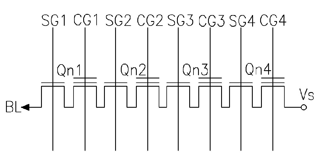
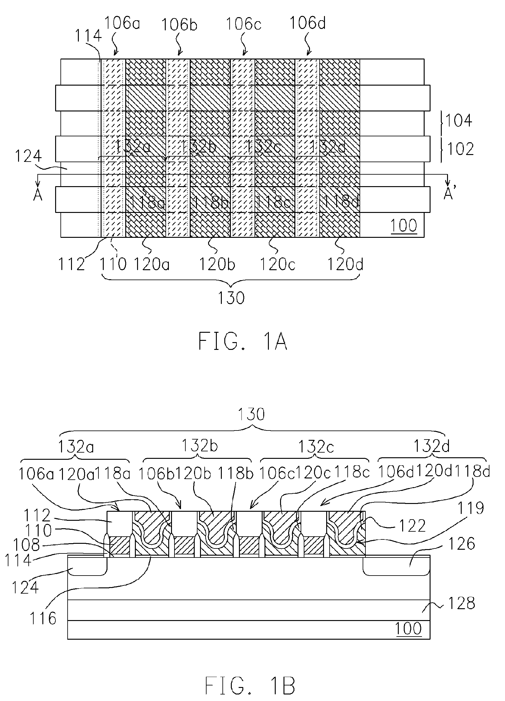
[0035]FIG. 1A shows a top view of a NAND type flash memory cell array of the present invention. FIG. 1B show the cross section (along A–A′ of FIG. 1A) of a NAND type flash memory cell array of the present invention.

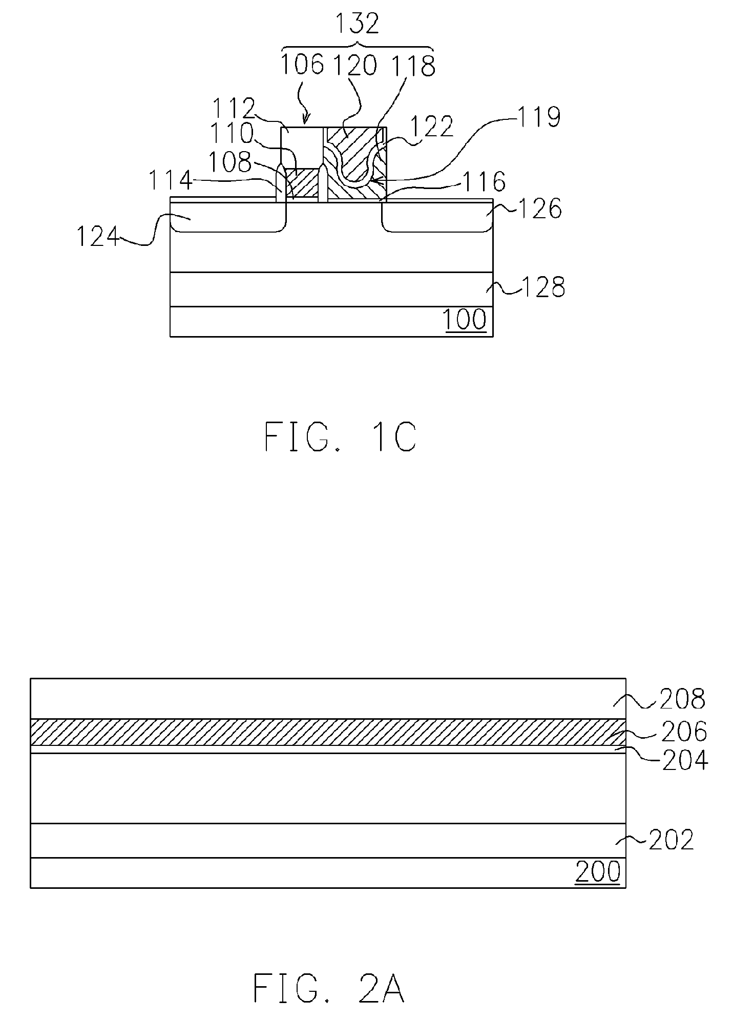
[0036]Referring to FIGS. 1A and 1B, the flash memory cell structure of the present invention comprise a substrate 100; a device insulating structure 102, an active region 104; a plurality of stacked gate structures 106a–106d, wherein each of the stacked gate structure includes a select gate dielectric layer 108, a select gate 110 and a gate cap layer 112); a spacer 114, a tunneling dielectric layer 116, a plurality of floating gates 118a–118d, a plurality of control gates 120a–120d, a plur...


PUM


Abstract

A flash memory cell array comprises a substrate, a string of memory cell structures and source region / drain region. Each of memory cell structures includes a stack gate structure including a select gate dielectric layer, a select gate and a gate cap layer formed on the substrate; a spacer is set on the sidewall of the select gate; a control gate connected to the stack gate structure is set on the one side of the stack gate structure; a floating gate is set between the control gate and the substrate; an inter-gate dielectric layer is set between the control gate and the floating gate; and a tunneling dielectric layer is set between the floating gate and the substrate. The source region / drain region is set in the substrate near outer control gate and stack gate structure of the flash memory cell array.

Description

CROSS-REFERENCE TO RELATED APPLICATION[0001]This application is a divisional of a prior application Ser. No. 10 / 604,819, filed Aug. 19, 2003, now U.S. Pat. No. 6,911,690.BACKGROUND OF THE INVENTION[0002]1. Field of the Invention[0003]This invention relates generally to a semiconductor device, and more particularly to a flash memory cell array and manufacturing method thereof.[0004]2. Background of the Related Art[0005]Flash memory is a non-volatile solid state memory that maintains data even after all power sources have been disconnected. Flash memory has been widely used in personal computers and other electronic equipment because of its programmable features allowing writing, erasing and reading data a number of times.[0006]A conventional flash memory cell is a transistor comprising a control gate, a doped polysilicon floating gate and an oxide layer separating these two gates from each other. A tunnel oxide layer separates the floating gate and the substrate. Because the floating...

Claims


Application Information

Patent Timeline
Patent Type & Authority Patents(United States)
IPC IPC(8): G11C16/04G11C13/00H01L21/8247H01L27/115
CPCG11C16/0483H01L27/11524H01L27/11521H01L27/115G11C16/0433H10B41/35H10B69/00H10B41/30
Inventor HSU, CHENG-YUANHUNG, CHIH-WEIWU, CHI-SHANHUANG, MIN-SAN
Owner POWERCHIP SEMICON MFG CORP
Why Eureka
Try Eureka