System and method for multiple signal carrier time domain channel estimation

a time domain channel and multiple signal carrier technology, applied in multi-frequency code systems, amplitude demodulation, baseband system details, etc., can solve problems such as air interface standards, intersymbol interference or distortion of received signals, and modulated carrier signals fading

Inactive Publication Date: 2006-06-06
INTEL CORP
View PDF3 Cites 45 Cited by
  • Summary
  • Abstract
  • Description
  • Claims
  • Application Information

AI Technical Summary

Problems solved by technology

Due to this misalignment, the multipath signals can cause intersymbol interference or distortion of the received signal.
The multiple paths traveled by the modulated carrier signal typically results in fading of the modulated carrier signal.
These existing air interface standards, however, have limitations and trade-offs that have motivated researchers to investigate ways to improve the quality and capacity of cellular communication systems.
In cellular communications systems, the wireless spectrum available for use is a limited resource.
For example, the previously described multipath distortions are caused by reflections of the signal from objects in the environment, and Doppler effects distort the signal when there are relative movements between the transmitter, receiver, and objects in the environment.
A limitation of this receiver system is that the interpolation filter is typically optimized for a generic channel, that may not be optimal for other channel settings.
For example, an interpolation filter that is optimal for a low delay spread channel may provide poor performance for a high delay spread channel.
Additionally, the interpolation filter is generally sensitive to noise and interference.
The primary limitation of the receiver system of FIG. 3 is sensitivity to noise and interference.
As a result, the time-domain response can be incorrectly estimated, leading to degradation of the estimation of the channel.
Another limitation is implementation complexity.
The IFFT unit 320 and the FFT unit 340 are generally complex and operationally require large amounts of computation time.
The prior art training systems are generally sensitive to noise and interference.
Fading and multipath can also cause problems.
Additionally, multiple carrier systems (such as OFDM) can suffer from time jitter, which limits the performance of prior art training systems.

Method used


Image

  • System and method for multiple signal carrier time domain channel estimation
  • System and method for multiple signal carrier time domain channel estimation
  • System and method for multiple signal carrier time domain channel estimation

Examples


Embodiment Construction

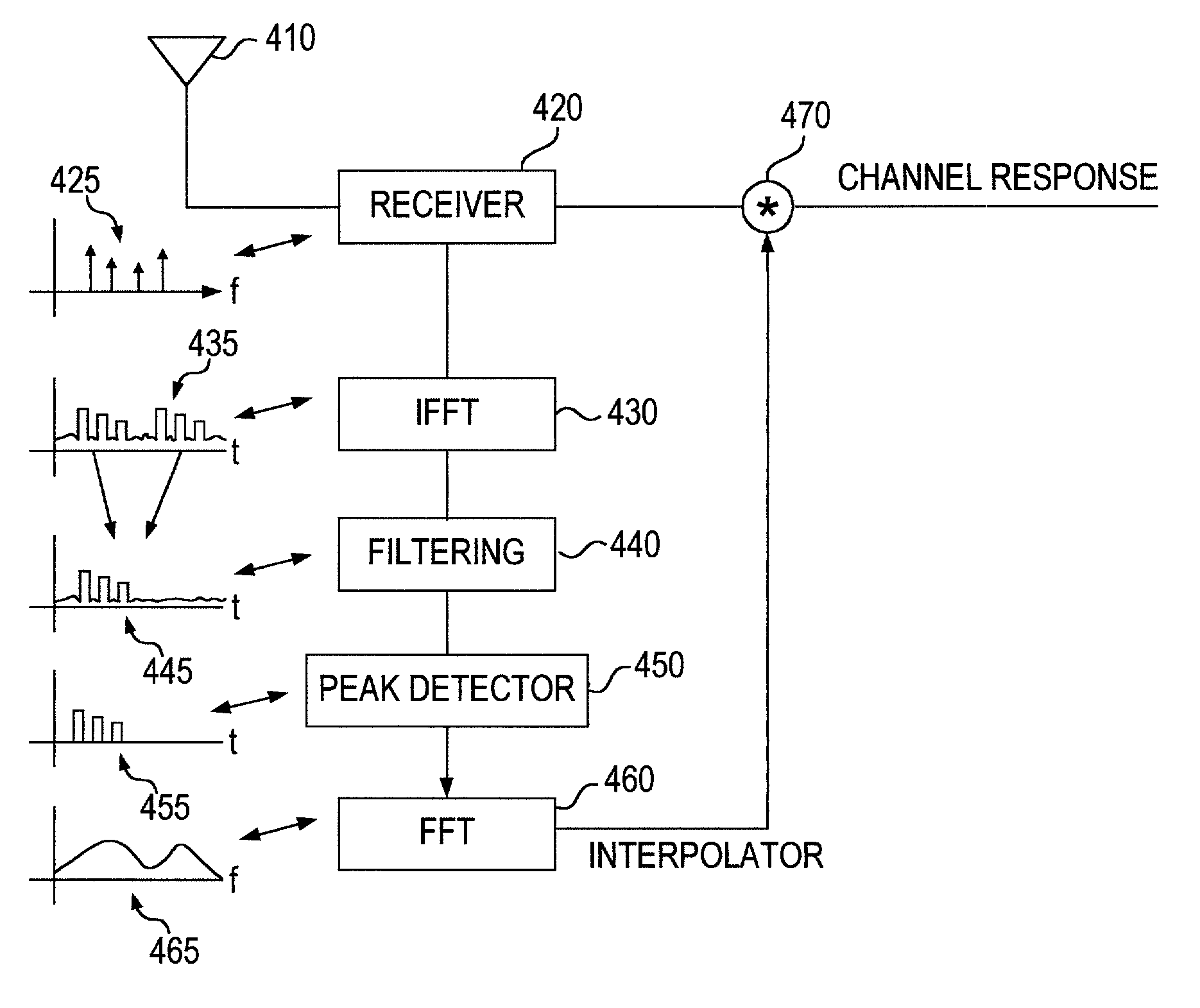
[0037]As shown in the drawings for purposes of illustration, the invention is embodied in an apparatus and a method for estimating a transmission channel between a transmitter and a receiver of a multiple carrier system.

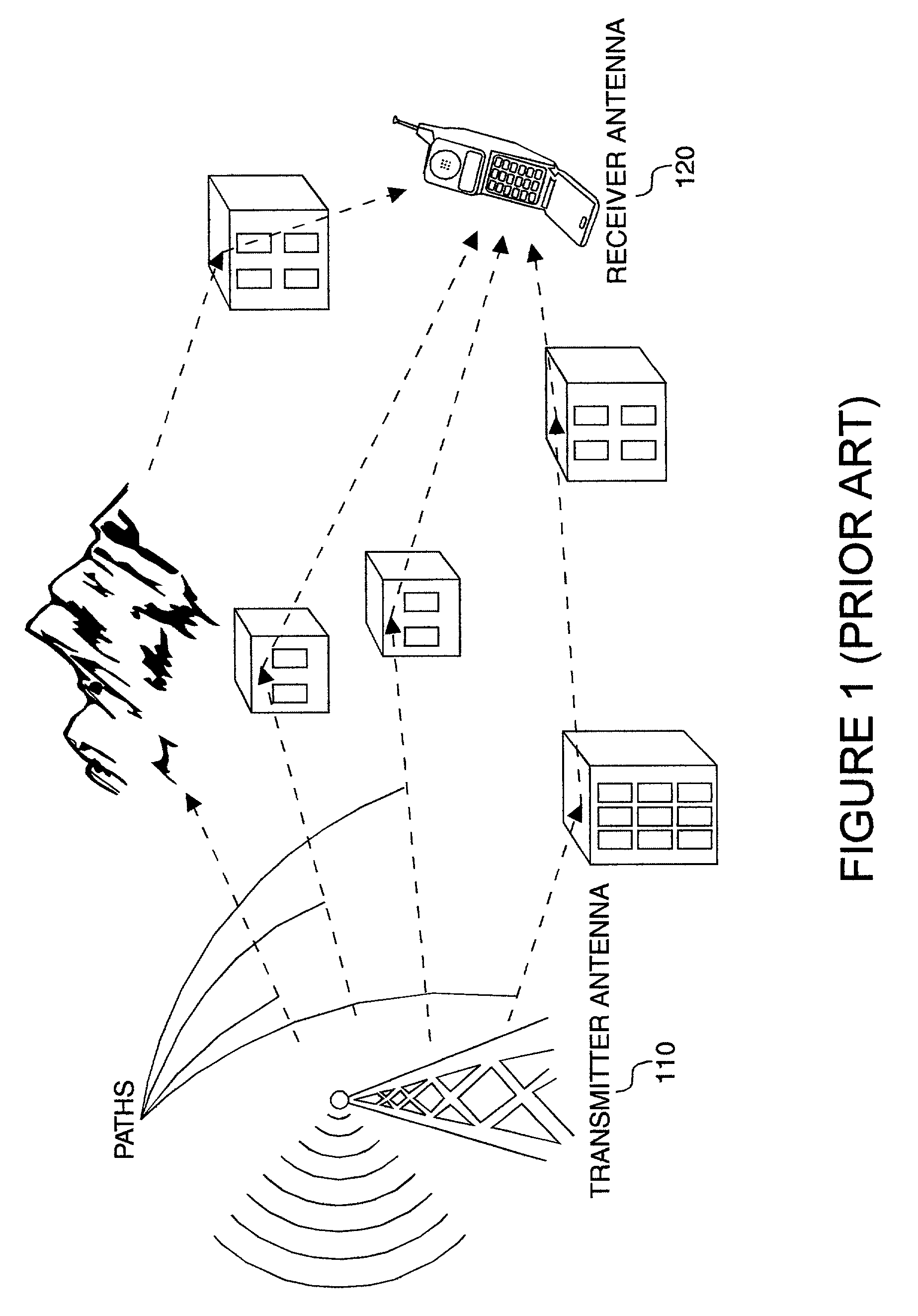
[0038]Particular embodiments of the present invention will now be described in detail with reference to the drawing figures. The techniques of the present invention may be implemented in various different types of wireless communication systems. Of particular relevance are cellular wireless communication systems. A base station transmits downlink signals over wireless channels to multiple subscribers. In addition, the subscribers transmit uplink signals over the wireless channels to the base station. Thus, for downlink communication the base station is a transmitter and the subscribers are receivers, while for uplink communication the base station is a receiver and the subscribers are transmitters. The subscribers may be mobile or fixed. Exemplary subscribers include...


PUM


Abstract

The present invention provides a method of characterizing a frequency response of a transmission channel between a transceiver and a subscriber unit. The method includes once per predetermined interval of time, the transceiver transmitting a signal including multiple carriers, a plurality of the carriers including training symbols, a plurality of the carriers including information symbols. The subscriber unit generates frequency response estimates at the frequencies of the carriers including training symbols, each interval of time. The frequency response estimates are converted into a time domain response generating an impulse response once per interval of time. The impulse responses are filtered over a plurality of intervals of time. A channel profile is determined from the filtered impulse responses. The channel profile is converted to the frequency domain generating a channel interpolator. The characterized frequency response is generated from the channel interpolator and the frequency response estimates. The filtering can include averaging the impulse responses over a plurality of intervals of time, accumulating the impulse responses over a plurality of intervals of time, or weighted averaging of the impulse responses over a plurality of intervals of time. The weighted averaging can be dependent upon a phase error between the impulse responses, and/or an amplitude error between the impulse responses.

Description

FIELD OF THE INVENTION[0001]The invention relates generally to methods and devices for wireless communications. More particularly, it relates to techniques for improved wireless transmission channel estimation.BACKGROUND OF THE INVENTION[0002]FIG. 1 show a prior art wireless system. The system includes modulated carrier signals traveling from a transmitter 110 to a receiver 120 following many different (multiple) transmission paths.[0003]Multipath can include a composition of a primary signal plus duplicate or echoed images caused by reflections of signals off objects between the transmitter and receiver. The receiver may receive the primary signal sent by the transmitter, but also receives secondary signals that are reflected off objects located in the signal path. The reflected signals arrive at the receiver later than the primary signal. Due to this misalignment, the multipath signals can cause intersymbol interference or distortion of the received signal.[0004]The actual receive...

Claims


Application Information

Patent Timeline
Patent Type & Authority Patents(United States)
IPC IPC(8): H04K1/10H04L27/28H04L25/02H04L27/26
CPCH04L25/0232H04L25/0222H04L25/022H04L27/2647
Inventor SAMPATH, HEMANTH
Owner INTEL CORP
Why Eureka
Try Eureka