System and method for panoramic imaging

a panoramic and image processing technology, applied in the field of panoramic imaging, can solve the problems of convergent rays of light that make up the reflected image, insufficient imaging or resolution, and large optical distortion in the resulting image, and achieve the effect of quick presentation to the user

Inactive Publication Date: 2006-06-06
360AI SOLUTIONS LLC
View PDF63 Cites 106 Cited by
  • Summary
  • Abstract
  • Description
  • Claims
  • Application Information

AI Technical Summary

Benefits of technology

[0012]The present invention provides a system for processing panoramic photographic images. In particular, the present invention combines a panoramic imaging system with at least one traditional pan, tilt and / or zoom camera. In one embodiment of the invention, a user may be presented with a wide-angle viewable panoramic image of a scene produced by the panoramic imaging system. The user may “look” at different portions of the viewable panoramic image, i.e. change the field of view of the viewable panoramic image, with a mouse, keyboard, head tracker device, or other pointing device. As the user is viewing different portions of the viewable panoramic image, at least one secondary camera coupled with a pan, tilt and / or zoom controller device, working in the background and unbeknownst to the user, will attempt to “keep up” with the user and move to the various portions of the scene that the user is viewing. The user may then indicate a particular portion of the viewable panoramic image that he or she would like to view in greater detail, and because of the narrow field of view that can be achieved via the pan, tilt and / or zoom controller device, the secondary camera will capture a high-resolution image of that portion of the scene once the camera has finished moving to the appropriate position. The high-resolution portion of the scene captured by the secondary camera may then be processed if necessary in order to correct, for example, the perspective angle, and the high-resolution portion of the scene may then be overlaid onto the appropriate corresponding portion of the wide-angle viewable panoramic image being displayed, presenting that particular portion of the panoramic image in greater detail. The result will be that the portion of the panoramic image the user is interested in will seamlessly become sharper and clearer. In another embodiment, a single camera including an active-pixel image sensor, such as a complementary metal-oxide semiconductor (CMOS) sensor, may be used in the panoramic imaging system, and a second camera will not be needed. In this embodiment, the CMOS camera can present a wide-angle viewable panoramic image of a scene to a user. When the user identifies a portion of the image that he or she is interested in, the windowing capabilities of the CMOS camera can be used to quickly present the user with a high-resolution image of that portion of the scene.

Problems solved by technology

A drawback to this is the fact that a typical 180-degree lens can cause substantial amounts of optical distortion in the resulting image.
Spherical mirrors have constant curvatures and are easy to manufacture, but do not provide optimal imaging or resolution.
A major drawback to this system lies in the fact that the rays of light that make up the reflected image converge at the focal point of the reflector.
As a result, positioning of the sensor relative to the reflecting surface is critical, and even a slight disturbance of the mirror will impair the quality of the image.
Another disadvantage is that the use of a perspective-projections model inherently requires that, as the distance between the sensor and the mirror increases, the cross-section of the mirror must increase.
This causes complications to arise with respect to the design of the image sensor optics.
A disadvantage of this system is that many of the light rays are not orthographically reflected by the parabolic mirror.
However, when this system is combined with a camera lens, the combination of the lens and the equi-angular mirror is no longer a projective device, and each pixel does not span exactly the same angle.
However, this system does not take into account the fact that there may be certain areas of the resulting panoramic image that a viewer may have no desire to see.
Therefore, some of the superior image resolution resources of the mirror are wasted on non-usable portions of the image.
One drawback of panoramic imaging is that the available resolution is reduced.
Therefore, panoramic images have inherently lower resolutions because of the large field of view that they cover.
However, these systems have disadvantages because a pan and tilt apparatus is inherently slow, and the user can experience motion blur and dizziness as the pan and tilt camera attempts to catch up and point in the direction that the user is pointing or looking.

Method used


Image

  • System and method for panoramic imaging
  • System and method for panoramic imaging
  • System and method for panoramic imaging

Examples


Embodiment Construction

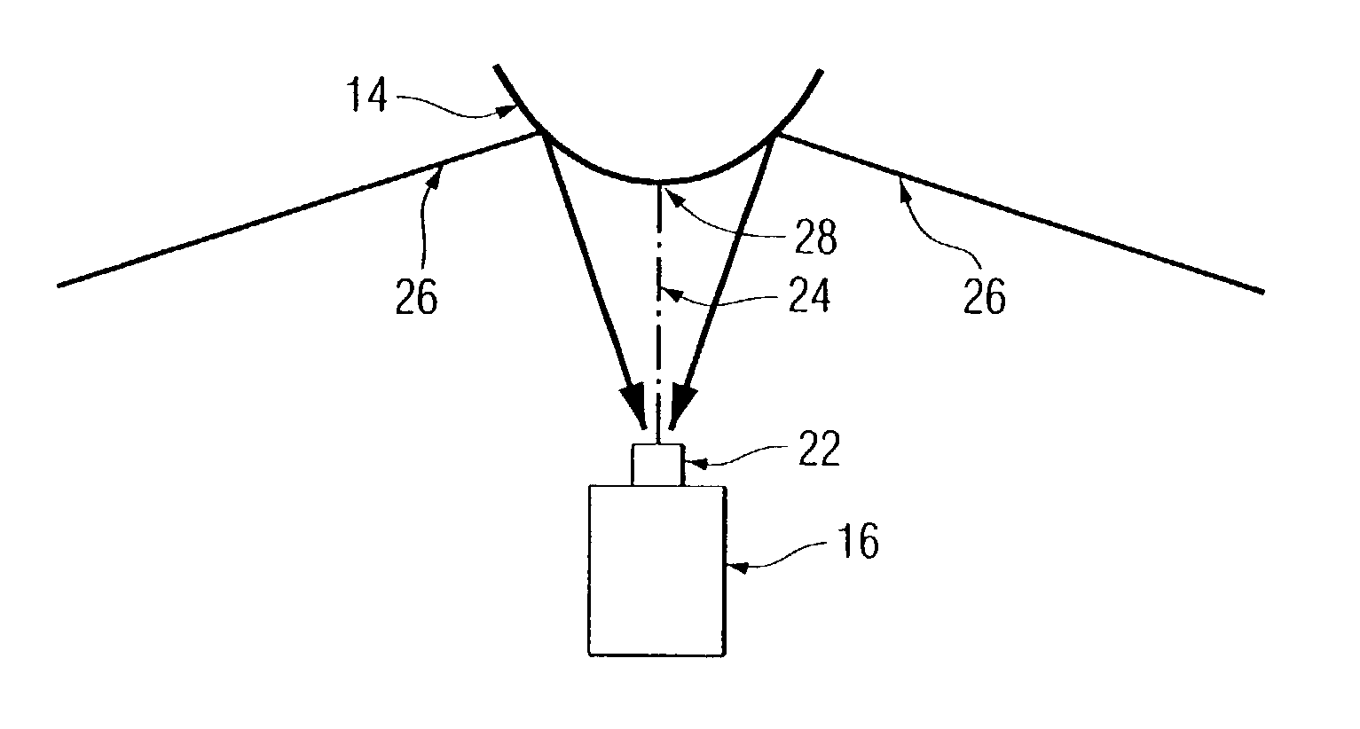
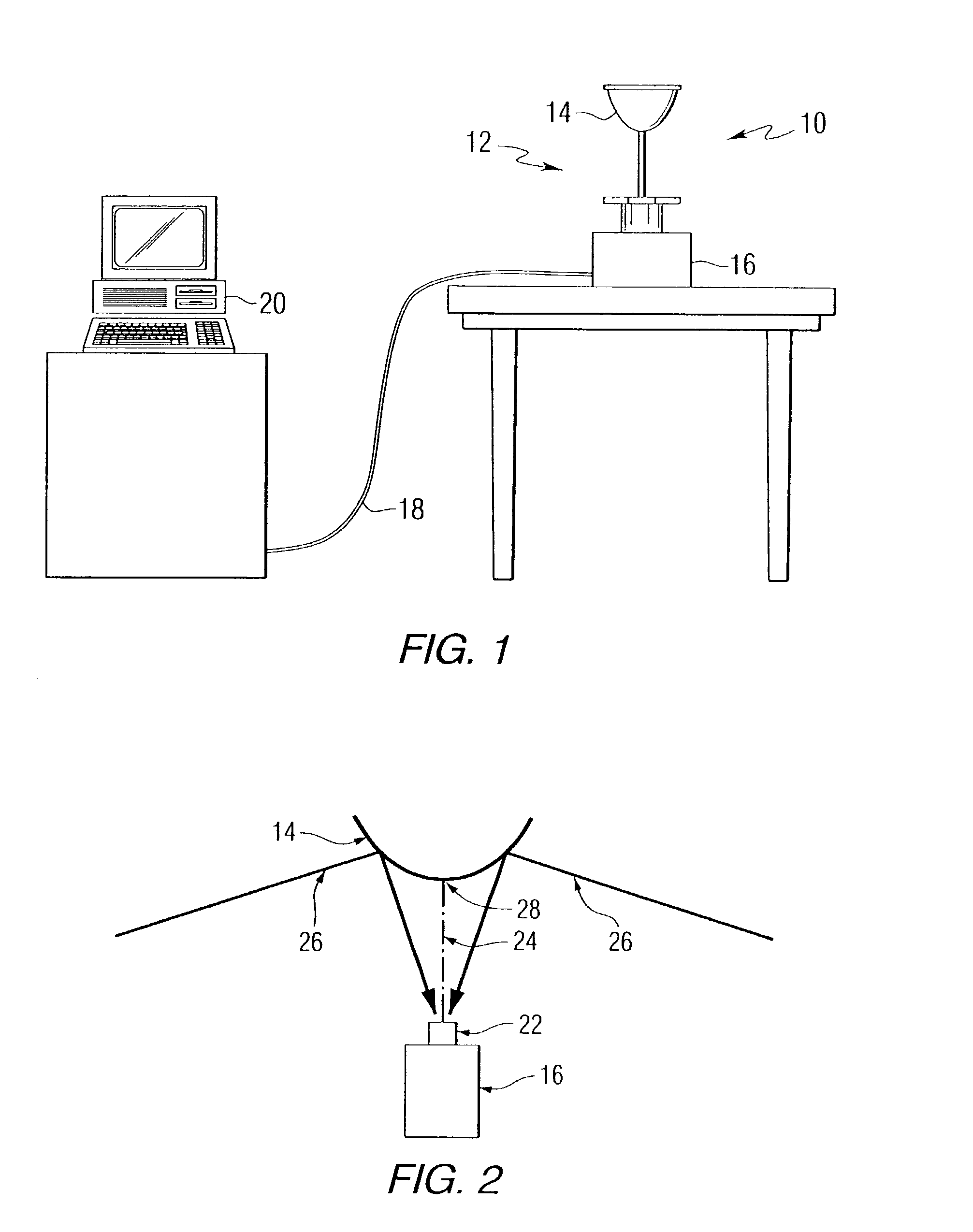
[0050]The present invention provides a system for processing photographic images. Referring to the drawings, FIG. 1 is a schematic representation of a system 10 for producing panoramic images. The system includes a panoramic imaging device 12, which can include a mirror 14 and a camera 16 that cooperate to capture and produce an image of a surrounding scene in the form of a two-dimensional array of pixels. In one embodiment, a digital converter device, such as a DV or IIDC digital camera connected through an IEEE-1394 bus, may be used to convert the captured image into pixel data. In another embodiment, the camera may be analog, and a digital converter device such as an analog to digital converter may be used to convert the captured image into pixel data. For the purposes of this invention, the pixels are considered to be an abstract data type to allow for the large variety of color models, encodings and bit depths. Each pixel can be represented as a data word, for example a pixel c...


PUM


Abstract

The present invention provides a system for processing panoramic photographic images. The system includes a mirror for reflecting an image of a scene, a mounting assembly for mounting the mirror on an axis, a first camera for capturing the image reflected by the mirror, at least one secondary camera for capturing a portion of the scene, means for mapping pixel data of the image captured by the first camera into a viewable image, and means for cooperatively displaying the viewable image and the portion of the scene captured by the at least one of the secondary cameras. The mirror may include a convex reflective surface defined by rotating around the axis: an equi-angular shape or a compensated equi-angular shape. The secondary camera may also capture a portion of the image reflected by the mirror. Alternatively, the system may include a single camera including an active-pixel image sensor for capturing at least a portion of the image reflected by the mirror. Methods for processing images in accordance with the system are also provided.

Description

CROSS-REFERENCE TO RELATED APPLICATIONS[0001]This application is a continuation-in-part of U.S. patent application Ser. No. 10 / 256,743 filed Sep. 26, 2002. This application also claims the benefit of U.S. Provisional Application Ser. No. 60 / 348,471 filed Oct. 29, 2001 and U.S. Provisional Application Ser. No. 60 / 346,717 filed Jan. 7, 2002.FIELD OF THE INVENTION[0002]The present invention relates to panoramic imaging, and more particularly relates to a system for processing panoramic photographic images.BACKGROUND INFORMATION[0003]Recent work has shown the benefits of panoramic imaging, which is able to capture a large azimuth view with a significant elevation angle. If instead of providing a small conic section of a view, a camera could capture an entire half-sphere or more at once, several advantages could be realized. Specifically, if the entire environment is visible at the same time, it is not necessary to move the camera to fixate on an object of interest or to perform explorat...

Claims


Application Information

Patent Timeline
Patent Type & Authority Patents(United States)
IPC IPC(8): G06K9/36G02B13/06
CPCG02B13/06G03B37/06G06T3/0062
Inventor SINGH, SANJIVRONDINELLI, MICHAELHERMAN, HERMAN
Owner 360AI SOLUTIONS LLC
Why Eureka
Try Eureka