Free-space optical communication apparatus and free-space optical communication system
Inactive Publication Date: 2006-06-06
CANON KK
View PDF10 Cites 22 Cited by
Summary
Abstract
Description
Claims
Application Information
AI Technical Summary
This helps you quickly interpret patents by identifying the three key elements:
Problems solved by technology
Method used
Benefits of technology
Benefits of technology
[0018]According to the present invention, on one occasion for communication between an free-space optical communication apparatus communicates with other free-space optical communication apparatuses, the time required for correcting the angle of an optical-beam reflecting mirror can be excluded, and the user of each of the apparatuses can be prevented from being aware of a delay. In addition, on the next occasion for the communication, optical communication can be performed, with the angle of the mirror corrected in accordance with the positional relationship between the apparatus and the other apparatuses.
[0023]According to the present invention, higher priority can freely be given either on the use of the first control mode to always communicate with each user at the optimal mirror angle, or on the use of the second control mode to perform high speed scanning without preventing each user from being aware of delay This enhances flexibility in operating the free-space optical communication system.
Problems solved by technology
Among the above systems of the related art, the optical-beam-direction correcting system including an accelerometer and a temperature sensor does not directly correct the direction of the emerging optical beam by performing automatic tracking.
Thus, it is impossible to ensure the correction.
Among the above systems of the related art, the optical-beam-direction correcting system including five arranged photodiodes has a problem in that, when scanning the communication apparatuses, it is impossible to perform the scanning at high speed, and therefore each communication apparatus is prevented from being aware of a delay because a long time is required to perform the steps of directing the mirror to a specified communication apparatus, reading the outputs of the five photodiodes, performing arithmetic operations, and correcting the optical beam direction by driving the mirror again.
Method used
Image
Click on the blue label to locate the original text in one second.
Reading with bidirectional positioning of images and text.
Examples
first embodiment
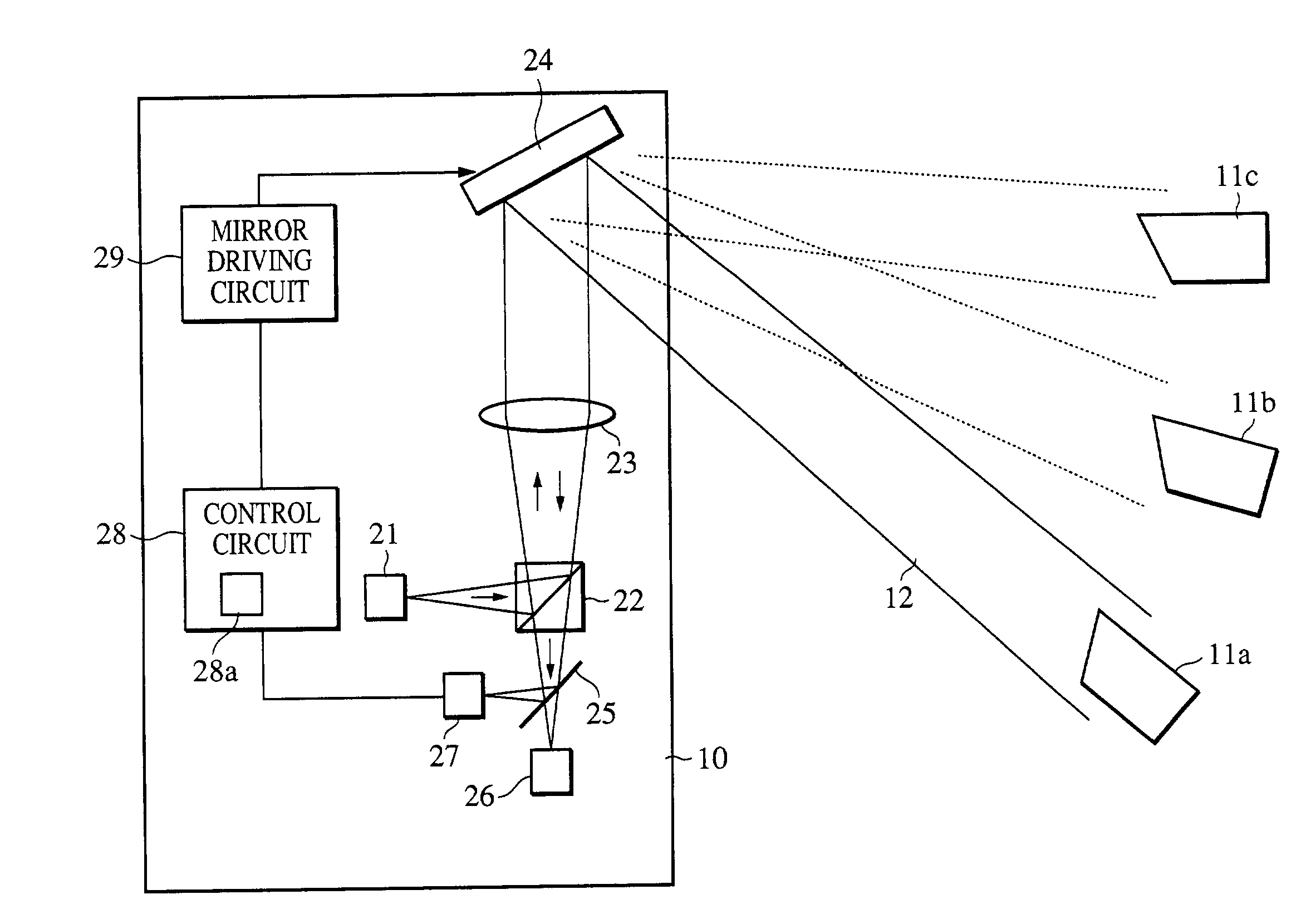
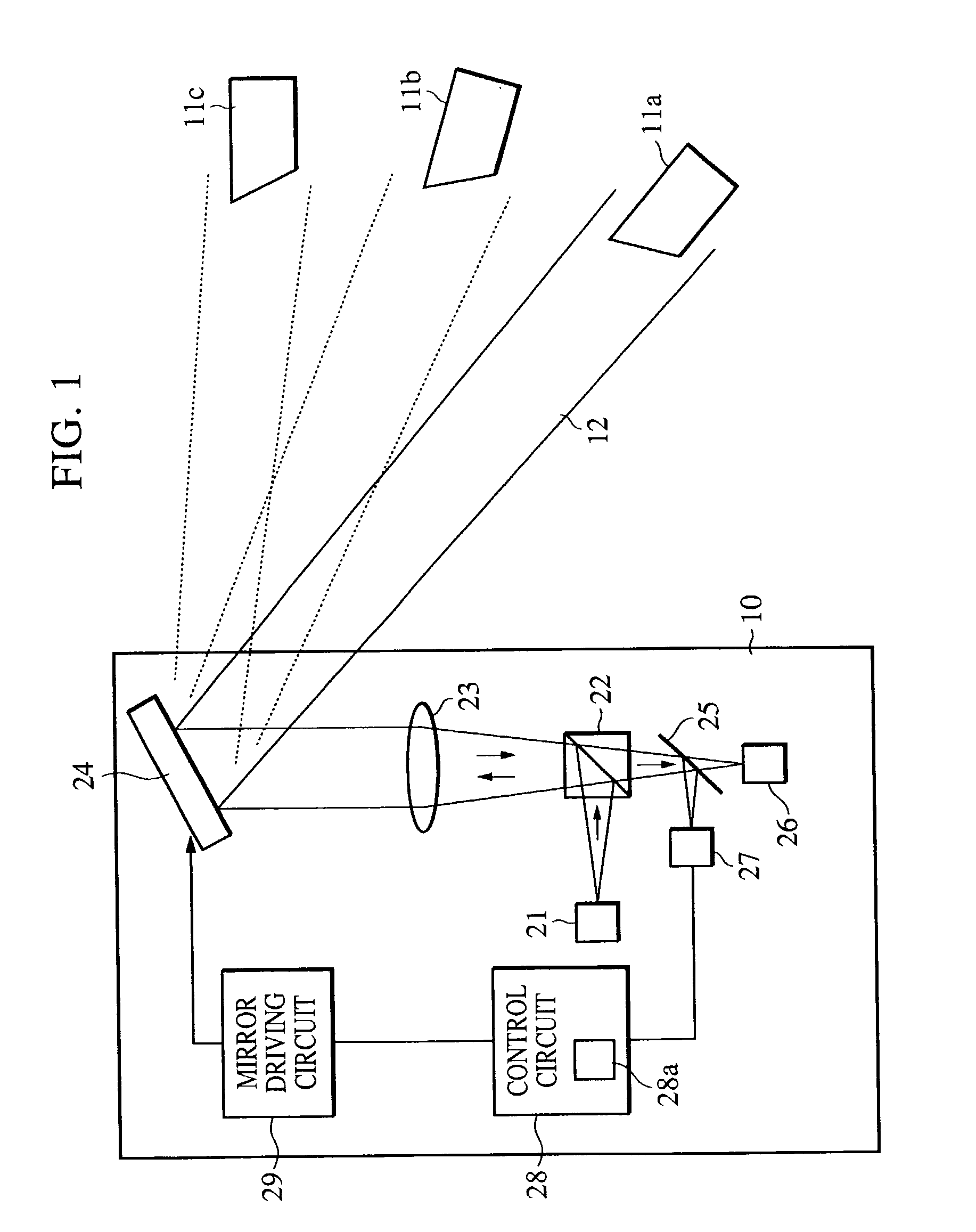
[0031]FIG. 1 shows the configuration of a free-space optical communication system according to a first embodiment of the present invention. This system includes a base apparatus 10 (free-space optical communication system). The base apparatus 10 sequentially scans an optical beam 12 over a plurality of other communication apparatuses 11a, 11b, and 11c, and performs bidirectional wireless communication with each of the communication apparatuses 11a, 11b, and 11c.
[0032]In the first embodiment, the communication apparatuses 11a to 11c are cyclically scanned in the order of the apparatus 11a, the apparatus 11b, the apparatus 11c, the apparatus 11a, . . . , in such a way that the apparatus 10 initiates communication with the apparatus 11b when ending communication with the apparatus 11a, and initiates communication with the apparatus 11c when ending communication with the apparatus 11b.
[0033]However, any scanning order may be used in the present invention. The present invention may use...
second embodiment
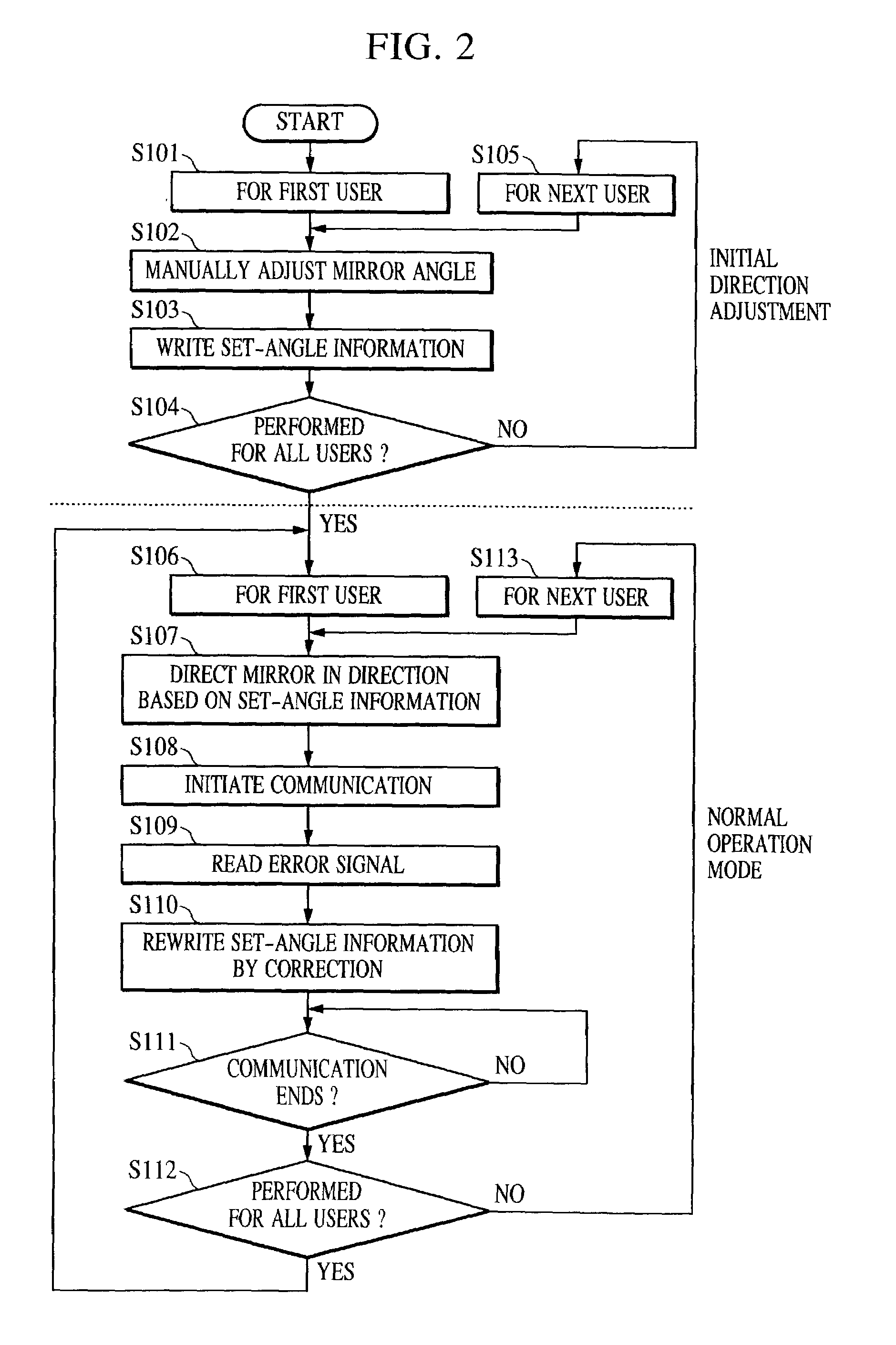
[0054]FIG. 3 is a flowchart showing a control process performed by an base apparatus included in a free-space optical communication system according to a second embodiment of the present invention.
[0055]Initial setting on the mirror angle in the setting of the apparatus 10 is similar to that in the first embodiment. However, in the first embodiment, if the posture of the apparatus 10 changes due to external force, etc., in the normal operation mode, actual correction of the mirror 24 is not performed until the next scanning of each user. Thus, the communication condition may depart from the optimal condition when the apparatus 10 has a large posture change.
[0056]Accordingly, in the second embodiment, when the error signal is large and exceeds a predetermined range, driving (i.e., the automatic tracking operation) for correcting the angle of the mirror 24 for a user with which the apparatus 10 is communicating is immediately performed (fistcontrol mode). After ending the communicati...
third embodiment
[0060]Although the second embodiment has described a case in which the first control mode or the second control mode is automatically selected by the control circuit 28 based on whether or not the error signal is out of the predetermined range, the first control mode or the second control mode may be selected, as required, by a user's operation.
[0061]This makes it possible to freely give higher priority either on the use of the first control mode to always communicate with each user at the optimal mirror angle, or on the use of the second control mode to perform high speed scanning without preventing each user from being aware of any delay, whereby flexibility in operating the free-space optical communication system can be enhanced.
PUM
Property
Measurement
Unit
Angle
aaaaa
aaaaa
Abstract
A free-space optical communication apparatus includes a storage unit which stores angle-setting information for the mirror for communicating with each of the plurality of other apparatuses, a mirror driving unit which drives the mirror to an angle corresponding to the stored angle-setting information, an optical detecting unit which, on one occasion for communicating with a specified communication apparatus among the plurality of other apparatuses, detects the incident state of an optical beam sent from the specified apparatus, and a control unit which, based on the detected incident state of the optical beam, determines angle-correcting information for correcting the stored angle-setting information for the specified apparatus, and which, on the next occasion for communicating with the specified apparatus, uses the mirror driving unit to drive the mirror to an angle corresponding to the angle-setting information corrected by the angle-correcting information.
Description
BACKGROUND OF THE INVENTION[0001]1. Field of the Invention[0002]The present invention relates to a free-space optical communicationsystem in which an optical beam transmitted in free space is used to perform wireless communication between a free-space optical communication apparatus provided at one point and other free-space optical communication apparatuses provided at a plurality of points.[0003]2. Description of the Related Art[0004]The system shown in FIG. 5 has been proposed as the above type of free-space optical communication system that uses an optical signal to perform wireless communication. The system in FIG. 5 performs optical communication between a central base 50 provided at a point and individual communication apparatuses 51a to 51c provided at a plurality of remote points.[0005]Referring to FIG. 5, an optical signal emitted from a light source 52 in the central base 50 is converted into a slightly broadened parallel optical beam 54 by an optical system 53. In the c...
Claims
Application Information
Patent Timeline
Application Date:The date an application was filed.
Publication Date:The date a patent or application was officially published.
First Publication Date:The earliest publication date of a patent with the same application number.
Issue Date:Publication date of the patent grant document.
PCT Entry Date:The Entry date of PCT National Phase.
Estimated Expiry Date:The statutory expiry date of a patent right according to the Patent Law, and it is the longest term of protection that the patent right can achieve without the termination of the patent right due to other reasons(Term extension factor has been taken into account ).
Invalid Date:Actual expiry date is based on effective date or publication date of legal transaction data of invalid patent.

