Hydro-lifter rock bit with PDC inserts

a technology of hydraulic lifter and insert, which is applied in the direction of drilling casings, drilling pipes, cutting machines, etc., can solve the problems of affecting the drilling life and peak effectiveness of roller cone rock bits, affecting the penetration rate of shear cutter bits, and affecting the wear of elements on shear cutter bits

Inactive Publication Date: 2006-06-13
SMITH INT INC
View PDF31 Cites 32 Cited by
  • Summary
  • Abstract
  • Description
  • Claims
  • Application Information

AI Technical Summary

Benefits of technology

[0011]In one embodiment, the invention is a rolling cone rock bit including a body, a leg formed from the body with an attached rolling cone, and a plurality of cutting elements mounted to the backface of the leg, the plurality of cutting elements having at least one cutting element extending to the gage diameter of the drill bit. Preferably, at least a majority of the cutting tips of the cutting elements extend to gage diameter. The cutting elements may be disposed in a curved row on the leading edge of the leg. This arrangement may similarly be constructed on a second leg of the drill bit, in which case it is preferred that the cutting elements on the first leg are staggered with respect to the cutting elements on the second leg to result in overlapping cutting elements in rotated profile. The drill bit may also include a mud ramp surface for the flow of drilling fluid from the bottom of a wellbore. The cutting elements of the rolling cone cutters may be of any suitable cutting design, and may or may not extend to gage diameter. In addition, the drill bit may have inserts around its periphery to protect the body of the drill bit and to stabilize the drill bit.

Problems solved by technology

However, although shear bits have been found to drill effectively in softer formations, as the hardness of the formation increases it has been found that the cutting elements on the shear cutter bits tend to wear and fail, affecting the rate of penetration (ROP) for the shear cutter bit.
Nonetheless, the drilling of the borehole causes considerable wear on the inserts of the roller cone rock bit, which affects the drilling life and peak effectiveness of the roller cone rock bit.
This wear is particularly severe at the corner of the bottom hole, on what is called the “gage row” of cutting elements.
The gage row inserts have the further problem that they are constantly entering and leaving the formation that can cause high impact side loadings and further reduce insert life.
The wear of the inserts on the drill bit cones results not only in a reduced ROP, but the wear of the corner inserts results in a borehole that is “under gage” (i.e. less than the full diameter of the drill bit).
Further, because it is not always apparent when a bit has gone under gage, an undergage drill bit may be left in the borehole too long.
Since a drill bit is not designed to ream an undergage borehole, damage may occur to the replacement bit, especially at the areas most likely to be short-lived and troublesome to begin with.
This decreases its useful life in the next section.
Because this can result in substantial expense from lost drill rig time as well as the cost of the drill bit itself, the wear of the inserts at the corner of the rolling cone rock bit is highly undesirable.
Another cause of wear to the inserts on a rock bit is the inefficient removal of drill cuttings from the bottom of the well bore.
In certain types of formations the rock fragments may be particularly numerous, large, or damaging, and accelerated wear and loss or breakage of the cutting inserts often occurs.
This wear and failure of the cutting elements on the rock bit results in a loss of bit performance by reduced penetration rates and eventually requires the bit to be pulled from the hole.
Inefficient removal of drilling fluid and drill cuttings from the bottom hole exacerbates the wear and failure of the cutting elements on the roller cones because the inserts impact and regrind cuttings that have not moved up the bore toward the surface.
Erosion of the cone shell (to which the inserts or teeth attach) can also occur in a roller cone rock bit from drill cuttings when the bit hydraulics are inappropriately directed, leading to cracks and damage to the shell.
Ineffective removal of drilling, fluid and drill cuttings can further result in premature failure of the seals in a rock bit from a buildup of drill cuttings and mud slurry in the area of the seal.

Method used


Image

  • Hydro-lifter rock bit with PDC inserts
  • Hydro-lifter rock bit with PDC inserts
  • Hydro-lifter rock bit with PDC inserts

Examples


Embodiment Construction

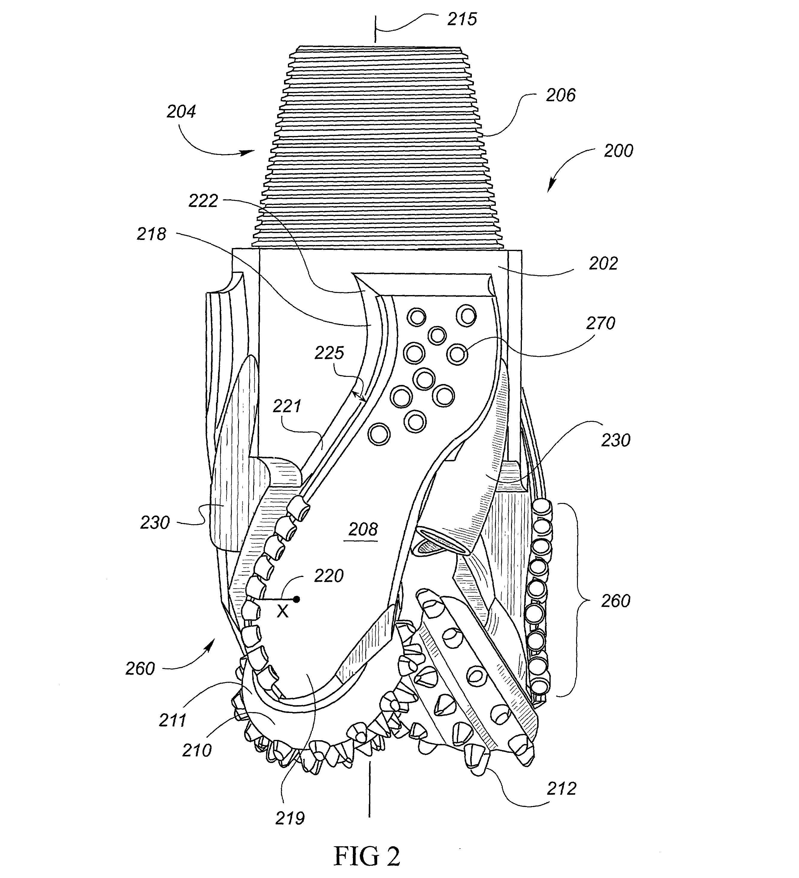
[0031]The rock bit 200 of FIG. 2 includes a body 202 and an upper end 204 that includes a readed pin connection 206 for attachment of a drill string used to raise, lower, and rotate bit 200 during drilling. Body 202 includes a number of legs 208, preferably three, each of which includes a mud lifter ramp 218 of width 225, a row of polycrystalline diamond cutters (PDC) 260, and wear resistant inserts 270. Each leg terminates at its lower end with a rotatable cone 210. Each cone 210 comprises a cone shell 211 and rows of cutting elements 212, or inserts, arranged in a generally conical structure. These inserts 212 may be tungsten carbide inserts (TCI) mounted in a pocket or cavity in the cone shell, or may be milled teeth on the face of the cone, as is generally known in the art. Each leg also includes a lubrication system which confines lubricant within bit 200 to reduce the friction in bearings located between rotatable cutters or cones 210 and their respective shafts. Semi-round to...


PUM


Abstract

A novel rolling cone rock bit includes a plurality of PDC or other cutters mounted to the leg of the drill bit and positioned to cut the troublesome corner of the bottomhole. The plurality of cutters may be the primary cutting component at gage diameter, or may be redundant to gage teeth on a rolling cutter that cut to gage diameter. Consequently, the occurrence of undergage drilling from the wear and failure of the gage row on a rolling cutter is lessened. Another inventive feature is the inclusion of a mud ramp that creates a large junk slot from the borehole bottom up the drill bit. The resulting pumping action of the drill bit ramp speeds up the removal of chips or drilling cuttings from the bottom of the borehole, reduces the level of hydrostatic pressure at the bottom of the borehole and minimizes the wearing effect of cone inserts regrinding damaging drill cuttings.

Description

CROSS-REFERENCE TO RELATED APPLICATIONS[0001]This is a divisional continuing application of U.S. patent application Ser. No. 09 / 589,260, filed Jun. 7, 2000 now U.S. Pat. No. 6,688,410.STATEMENT REGARDING FEDERALLY SPONSORED RESEARCH OR DEVELOPMENT[0002]Not Applicable.BACKGROUND OF THE INVENTION[0003]Rock bits, referred to more generally as drill bits, are used in earth drilling. Two predominant types of rock bits are roller cone rock bits and shear cutter bits. Shear cutter bits are configured with a multitude of cutting elements directly fixed to the bottom, also called the face, of the drill bit. The shear bit has no moving parts, and its cutters scrape or shear rock formation through the rotation of the drill bit by an attached drill string. Shear cutter bits have the advantage that the cutter is continuously in contact with the formation and see a relatively uniform loading when cutting the gage formation. Furthermore, the shear cutter is generally loaded in only one direction. ...

Claims


Application Information

Patent Timeline
Patent Type & Authority Patents(United States)
IPC IPC(8): E21B10/18E21B10/16E21B10/52E21B17/10
CPCE21B10/16E21B17/1092E21B10/52E21B10/18
Inventor SINGH, AMARDEEPNGUYEN, QUAN V.HUANG, SUJIAN
Owner SMITH INT INC
Why Eureka
Try Eureka