Compact LED module and projection display adopting the same

a technology of led modules and projection displays, applied in waveguides, instruments, lighting and heating apparatus, etc., can solve the problems of complicated illumination systems of conventional projection displays, short life span, and deterioration of light efficiency, and achieve the effect of efficient irradiation of light beams

Active Publication Date: 2006-06-13
SAMSUNG ELECTRONICS CO LTD
View PDF8 Cites 50 Cited by
  • Summary
  • Abstract
  • Description
  • Claims
  • Application Information

AI Technical Summary

Benefits of technology

[0017]Apparatuses consistent with the present invention provide a compact light source module including a collimator to collimate a light beam emitted from a compact light source such as an LED so as to efficiently irradiate the light beam onto an object within the range of a radiation angle, and a projection display adopting the compact light source module.
[0020]According to another aspect of the present invention, there is provided a projection display including an illumination unit, an optical modulator to modulate a light beam radiating from the illumination unit to be suitable for image data, and projection optics to magnify and project the light beam emitted from the optical modulator. The illumination unit includes at least one compact light source module. The at least one compact light source module includes a compact light source and a collimator including a parabolic first reflective surface to reduce a radiation angle at which a light beam radiates from the compact light source, so as to emit the light beam through a side aperture and a plane second reflective surface which is located under the first reflective surface and includes an incident portion through which the light beam radiates from the compact light source. The compact light source is located in the vicinity of a focal point of the first reflective surface.
[0021]According to still another aspect of the present invention, there is provided a compact light source module including: a compact light source; and a collimator including a parabolic first reflective surface to reduce a radiation angle at which a light beam radiates from the compact light source, so as to emit the light beam through a side aperture. The compact light source is located in the vicinity of a focal point of the first reflective surface.

Problems solved by technology

However, in such a conventional projection display, a lamp is used as a light source to illuminate optical modulators and has a short life span.
As a result, light efficiency deteriorates.
As a result, the additional use of the secondary optics makes an illumination system of the conventional projection display complicated and increases cost of manufacturing the illumination system.
However, since the secondary optics has to be lenses, light condensing efficiency deteriorates.
Accordingly, when the array of LEDs as shown in FIG. 4B is used, light is lost, resulting in decreasing light condensing efficiency and the luminance of the projection display.

Method used


Image

  • Compact LED module and projection display adopting the same
  • Compact LED module and projection display adopting the same
  • Compact LED module and projection display adopting the same

Examples


Embodiment Construction

[0038]Hereinafter, illustrative, non-limiting embodiments of the present invention will be described in detail with reference to the attached drawings. Like reference numerals refer to like elements throughout.

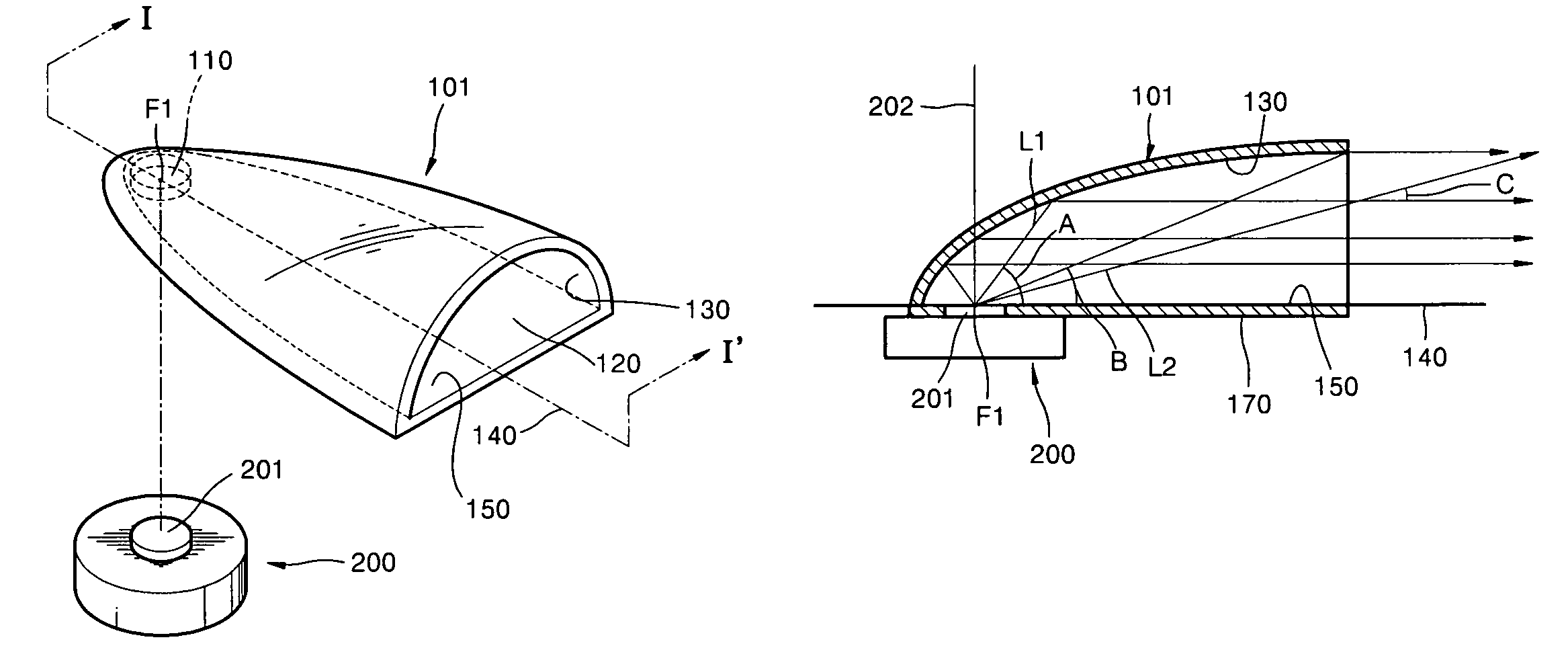
[0039]FIG. 5 is an exploded perspective view of a compact light source module, according to an embodiment of the present invention, and FIG. 6 is a cross-sectional view taken along line I–I′ of FIG. 5. Referring to FIGS. 5 and 6, an LED 200 is used as the compact light source. A collimator 101 is prepared on the LED 200. The LED 200 includes an LED chip 201 which emits a light beam. Although not shown, the LED 200 further includes a heat emitter which emits heat generated from the LED chip 201, and an anode and a cathode which supply the LED chip 201 with a current. In the present embodiment, the LED 200 does not include the dome lens 62 of FIG. 2. This does not limit the scope of the present invention. The structure of the LED 200 is well known to one of ordinary skill in the...


PUM


Abstract

A compact light source module includes a compact light source and a collimator that includes a parabolic first reflective surface to reduce a radiation angle at which a light beam radiates from the compact light source, so as to emit the light beam through a side aperture and a plane second reflective surface which is located under the first reflective surface and comprises an incident portion through which the light beam radiates from the compact light source. The compact light source is located in the vicinity of a focal point of the first reflective surface.

Description

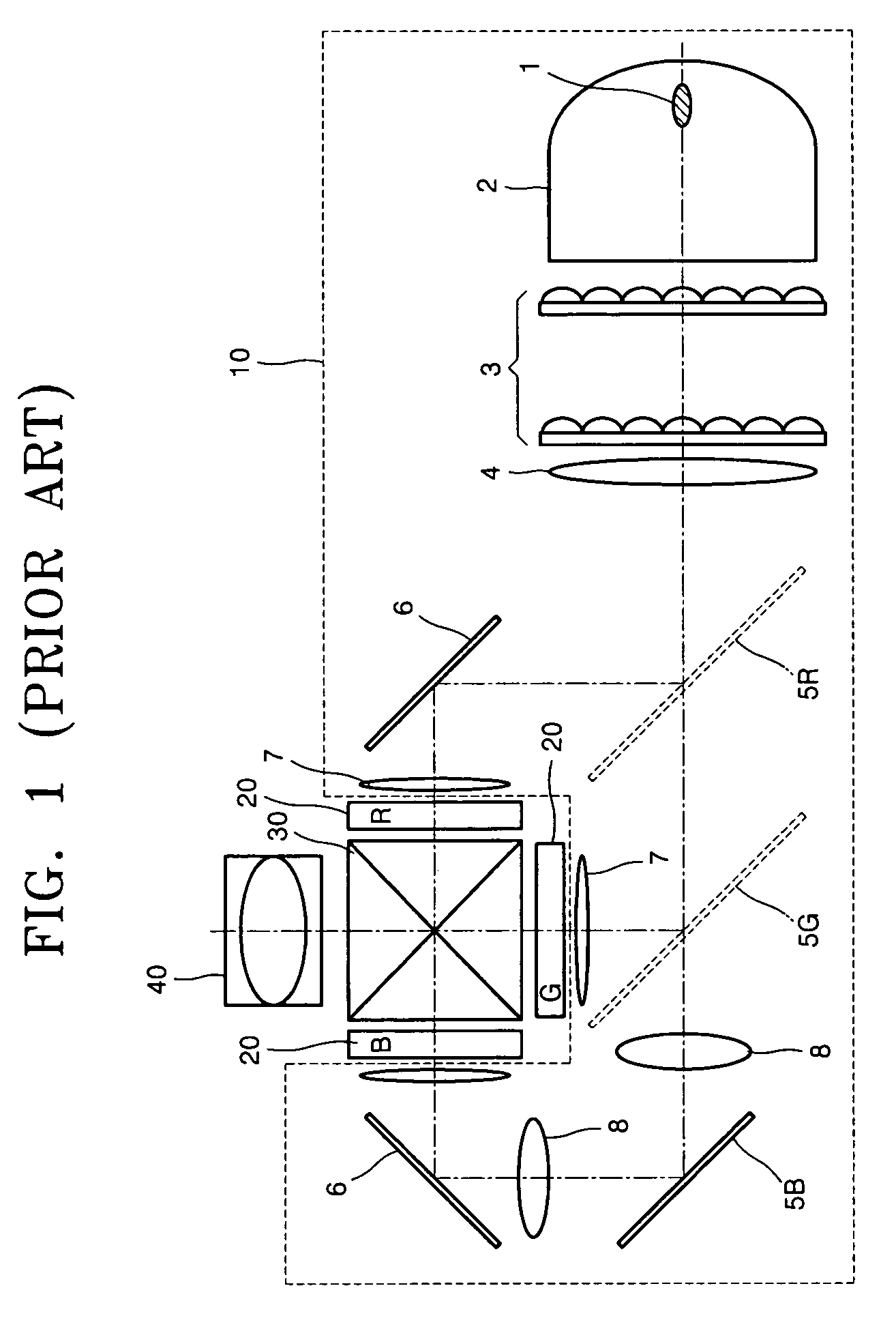
BACKGROUND OF THE INVENTION[0001]This application claims the priority of Korean Patent Application Nos. 2003-64207 and 2004-18284 filed in the Korean Intellectual Property Office on Sep. 16, 2003, and Mar. 18, 2004, respectively, and U.S. Provisional Patent Application No. 60 / 477,035 filed in the United States Patent and Trademark Office on Jun. 10, 2003, the disclosures of which are incorporated herein in their entirety by reference.[0002]1. Field of the Invention[0003]Apparatuses consistent with the present invention relate to a compact light source module and a projection display adopting the compact light source module and, more particularly, to a compact light source module using a light source such as a light emitting diode and a projection display adopting the compact light source module.[0004]2. Description of the Related Art[0005]FIG. 1 shows the structure of a conventional projection display. Referring to FIG. 1, the conventional projection display includes liquid crystal ...

Claims


Application Information

Patent Timeline
Patent Type & Authority Patents(United States)
IPC IPC(8): G03B21/14F21V7/04G01D11/28G02B6/10G03B21/28G02B27/18F21V7/00H01L33/60H01L33/64
CPCF21V7/0091G02B6/0023G02B6/0096G03B21/28H04N9/3152G02B6/4298F21Y2101/02G02B6/0031Y10S385/901H01L33/60H01L33/64F21Y2115/10G02B27/18
Inventor LEE, YOUNG-CHOLKURATOMI, YASUNORIKIM, DONG-HAMOON, IL-KWEON
Owner SAMSUNG ELECTRONICS CO LTD
Why Eureka
Try Eureka