Electrical connection structure for conductor formed on glass surface

a technology of electric connection and glass surface, which is applied in the direction of coupling contact parts, coupling device connections, coupling contact members, etc., can solve the problems of increasing the number of parts, reducing the strength of glass, and becoming impossible to use a solder containing. , to achieve the effect of reducing the number of parts, and easy disconnection of the connection member

Active Publication Date: 2006-06-13
ASAHI GLASS CO LTD
View PDF45 Cites 28 Cited by
  • Summary
  • Abstract
  • Description
  • Claims
  • Application Information

AI Technical Summary

Benefits of technology

[0013]The present invention is based on the idea of providing a cover member on a glass surface, inserting a connection member into a cavity formed by the cover member so as to elastically deform the connection member and pressing a conductor formed on a glass surface with the connection member to make them contact electrically. Since the above-mentioned construction does not require soldering, various problems caused by employing solder can be solved, and an exchange of parts is easy.
[0014]Further, it is preferred that the cover member and the connection member have respectively a structure fitting or engaging with each other. By fitting or engaging the cover member and the connection member with each other, disconnection of the connection member due to an external force can be prevented and the connection between the connection member and the conductor can be stabilized.
[0015]Further, it is preferred that one end of the connection member has elasticity and the other end of the connection member is a male type or female type terminal for a connector connected with a lead wire. When the connection member has a male type or female type terminal used conventionally, a conventional connector of a lead-wire-side can be used and no procurement of new parts or capital investment is necessary.
[0016]Alternatively, it may be such that one end of the connection member has elasticity and the other end of the connection member is connected with a lead wire by caulking. If the connection member is directly connected with a lead wire, it is possible to reduce the number of parts and lower the cost.
[0017]Further, it is preferred that a contact portion of the connection member to be in contact with the conductor be applied with a metal plating at the surface. By applying the connection member with a metal plating, it becomes possible to stabilize the connection with the conductor for long period of time.

Problems solved by technology

However, since the terminal 43 is attached to the baked silver paste 2 by soldering, there is a risk that the strength of the glass can be reduced by a thermal shock at the time of soldering.
Further, since the solder used for a window glass for automobiles usually contains lead, much work is needed in treating the solder containing lead at a time of disposing the glass.
Moreover, as in the ELV (End Life of Vehicle) order and WHEE&RoHS (Waste Electrical and Electronic Equipment & Restriction of the use of certain Hazardous Substances in electrical and electronic equipment) order in Europe, for example, regulations regarding the use of a solder containing lead are being considered in many countries and it is becoming impossible to use a solder containing lead.
However, according to the invention described in the specification of U.S. Pat. No. 4,707,591, the structure of the body becomes complicated in terms of attaching the contactor to the body flange, and since there is an individual difference of glass sheets in the radius, the degree of pressing of the contactor against the bus bar portion changes, which has been making the design of body complicated.
However, since the structure is composed of many parts and its assembly is complicated, it costs much, and insertion and pulling-off of the intervening terminal is difficult.

Method used


Image

  • Electrical connection structure for conductor formed on glass surface
  • Electrical connection structure for conductor formed on glass surface
  • Electrical connection structure for conductor formed on glass surface

Examples


example 1

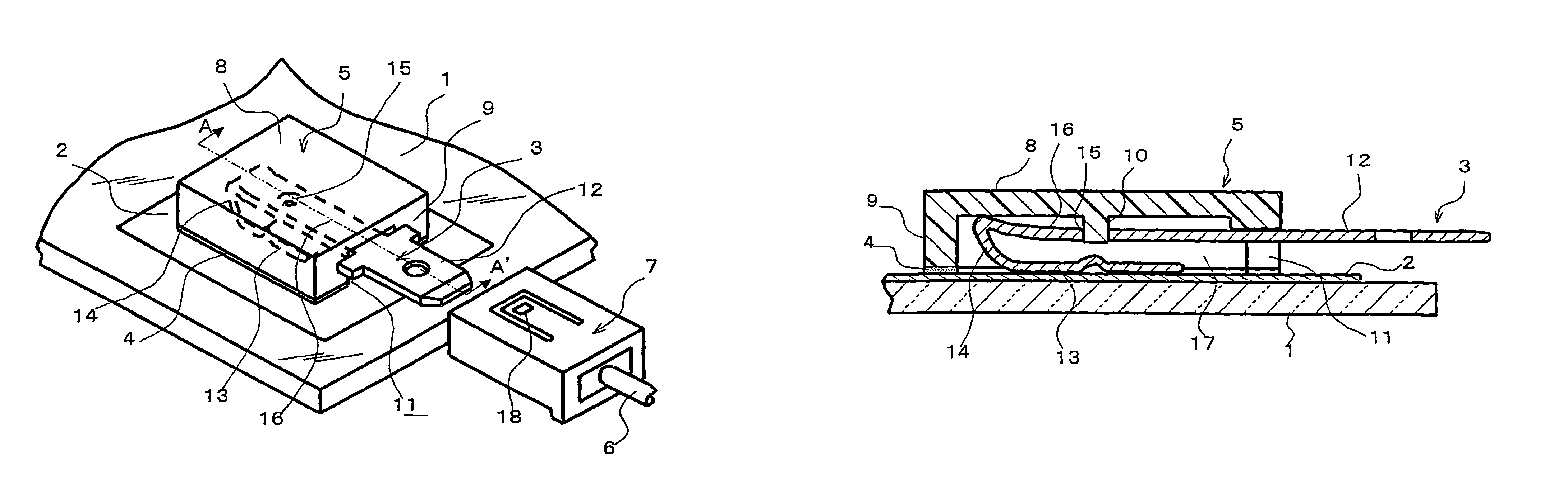
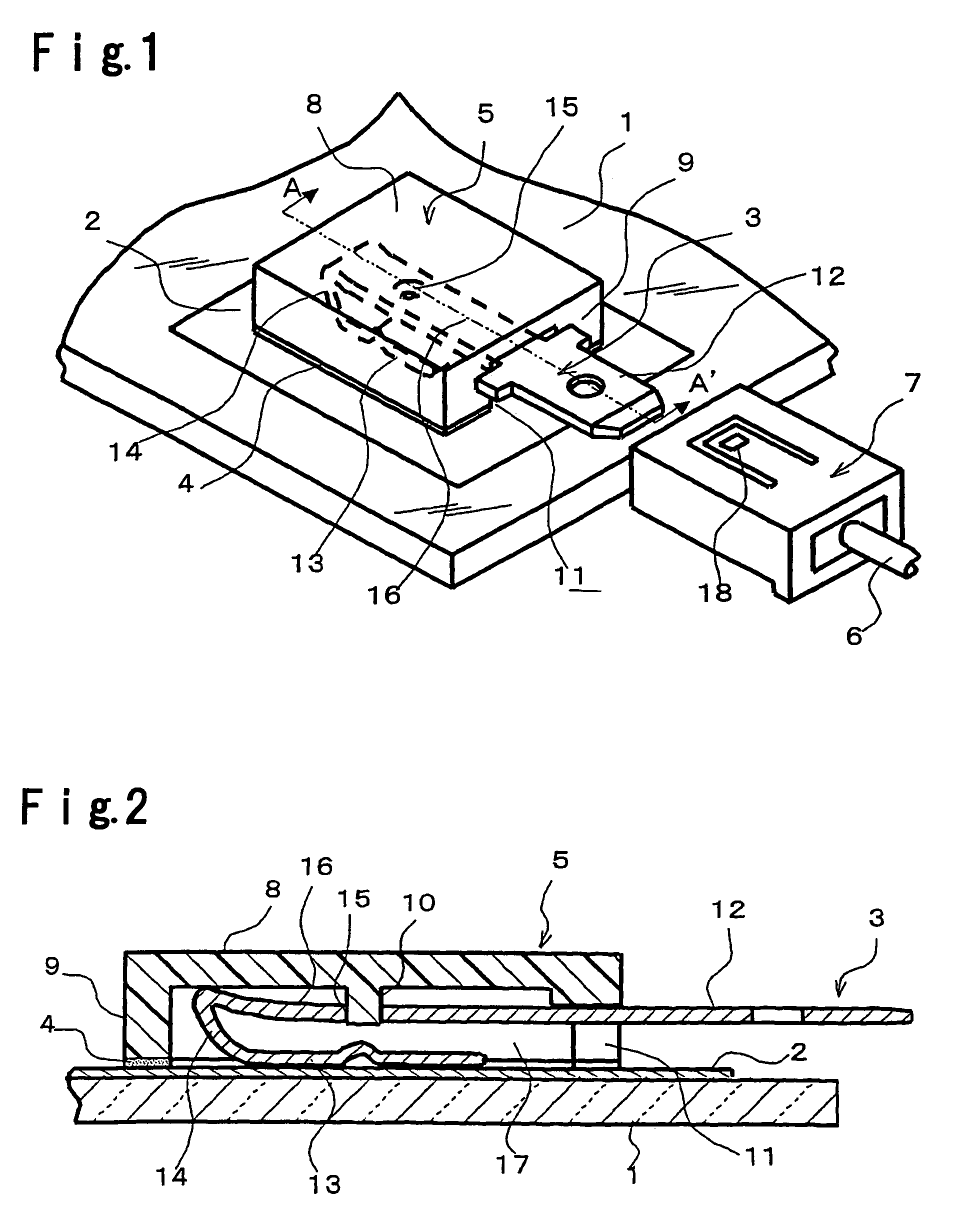
[0043]A cover member 5 having the shape shown in FIGS. 1 and 2 was made by cutting a polyamide resin having a size of 18 mm×12 mm and a thickness of 4 mm. Further, as an adhesive layer 4, a double-sided adhesive tape (manufactured by Sumitomo 3M Limited) of 0.4 mm thick cut into a shape corresponding to the bonding surface of the cover member 5, was employed to bond the cover member 5 at a predetermined position of the conductor 2 formed by baking a silver paste on a glass sheet 1.

[0044]The terminal member 3 comprises an insertion portion made of a beryllium copper of 0.3 mm thick and a terminal portion 12 made of a bronze of 0.8 mm thick welded to the insertion portion. The terminal portion 3 has a size complying with JIS-D5403 PA type male blade (with shoulders) for automobiles. The insertion portion has a width of 4.5 mm, a length of 10 mm and a height in a free space of 3.0 mm.

[0045]The terminal member 3 was inserted into the insertion slot 11 by pushing the insertion portion 16...

example 2

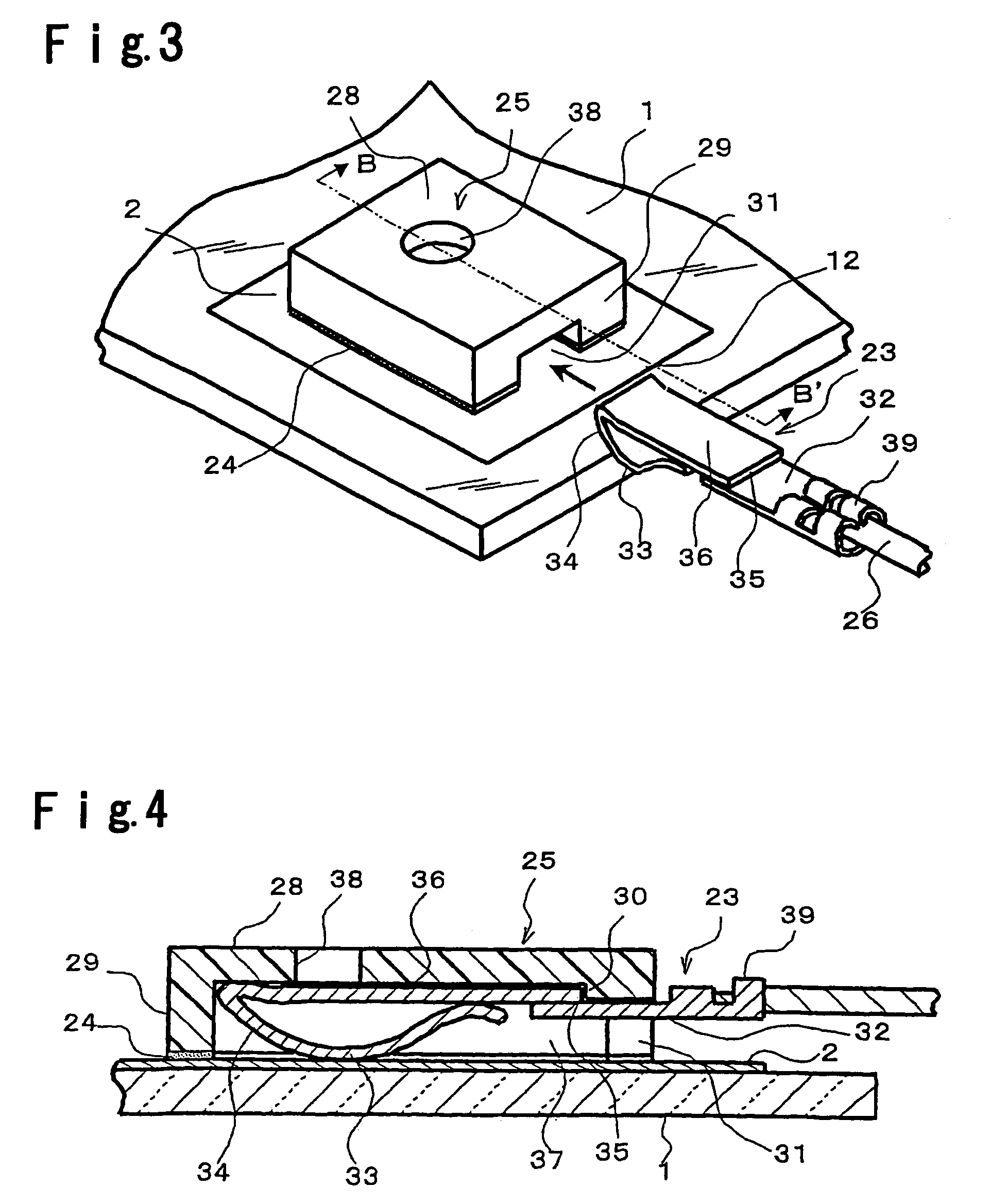
[0047]A cover member 25 having the shape shown in FIGS. 3 and 4 was made by cutting a polyamide resin having a size of 16 mm×15 mm and a thickness of 2.6 mm. Further, as an adhesive layer 24, a double-sided adhesive tape (manufactured by Sumitomo 3M Limited) of 0.4 mm thick cut into a shape corresponding to the bonding surface of the cover member 25, was employed to bond the cover member 25 at a predetermined position of a conductor 2 formed by baking a silver paste on a glass sheet 1.

[0048]The terminal member 23 comprises an insertion member made of a beryllium copper of 0.2 mm thick and a caulking portion 39 made of bronze of 0.3 mm thick welded to the insertion member. The insertion member has a width of 4.3 mm, a length of 10 mm and a height in a free space of 2.5 mm. Further, the caulking portion 39 has a length of 10 mm, a width of about 3.5 mm and a height of about 3 mm when it is caulked or crimped together with a lead wire 26.

[0049]The terminal member 23 was pushed into the...


PUM


Abstract

A conductor formed on a glass surface and a lead wire are electrically connected by a structure constituted by a small number of parts, which requires no soldering and achieves space-saving and low cost.An electrical connection structure for a conductor formed on a glass surface, comprising a conductor 2 formed on a glass surface, a cover member 5 made of an electrically insulating material forming a cavity 17 between the cover member 5 and the glass surface and having an insertion slot 11 communicating with the cavity 17, and a connection member 3 made of an electrically conductive material having elasticity and inserted into the insertion slot 11, wherein the connection member 3 and the conductor 2 are pressed to each other by the elasticity of the connection member 3 whereby they are electrically connected.

Description

TECHNICAL FIELD[0001]The present invention relates to an electrical connection structure for a conductor formed on a glass surface, for electrically connecting a conductor formed on a glass surface with a lead wire.BACKGROUND ART[0002]Various functions are added to a window glass for automobiles in recent years. In particular, to a rear window glass, an antenna function for receiving e.g. AM, FM or TV waves, or a defog function for defogging the window glass, is added by forming a baked silver paste on the glass surface. In order to exhibit these functions, it is necessary to supply electricity via a bus bar portion made of a baked silver paste. The supply of electricity is achieved by soldering a terminal having a shape shown as PA or PV type flat-type male terminal for automobiles defined by JIS-D5403 to the bus bar portion, and by connecting a connector connected with a lead wire, with the terminal.[0003]FIG. 5 is a perspective view showing a conventional structure in that a term...

Claims


Application Information

Patent Timeline
Patent Type & Authority Patents(United States)
IPC IPC(8): H01R13/62H01R4/50H01R13/20H01R13/24H01R13/627
CPCH01R13/20H01R13/2442H01R4/5066H01R2201/02H01R13/6272H01R4/48
Inventor HISAEDA, KATSUMITAKEUCHI, SHOICHI
Owner ASAHI GLASS CO LTD
Why Eureka
Try Eureka