Methods for making a supported graft

a vascular graft and supported technology, applied in the field of intraluminal grafts, can solve the problems of inconvenient intraluminal stent placement, inconvenient use, and insufficient diametric mechanical rigidity of conventional eptfe vascular grafts,

Inactive Publication Date: 2006-06-13
BARD PERIPHERAL VASCULAR
View PDF147 Cites 59 Cited by
  • Summary
  • Abstract
  • Description
  • Claims
  • Application Information

AI Technical Summary

Benefits of technology

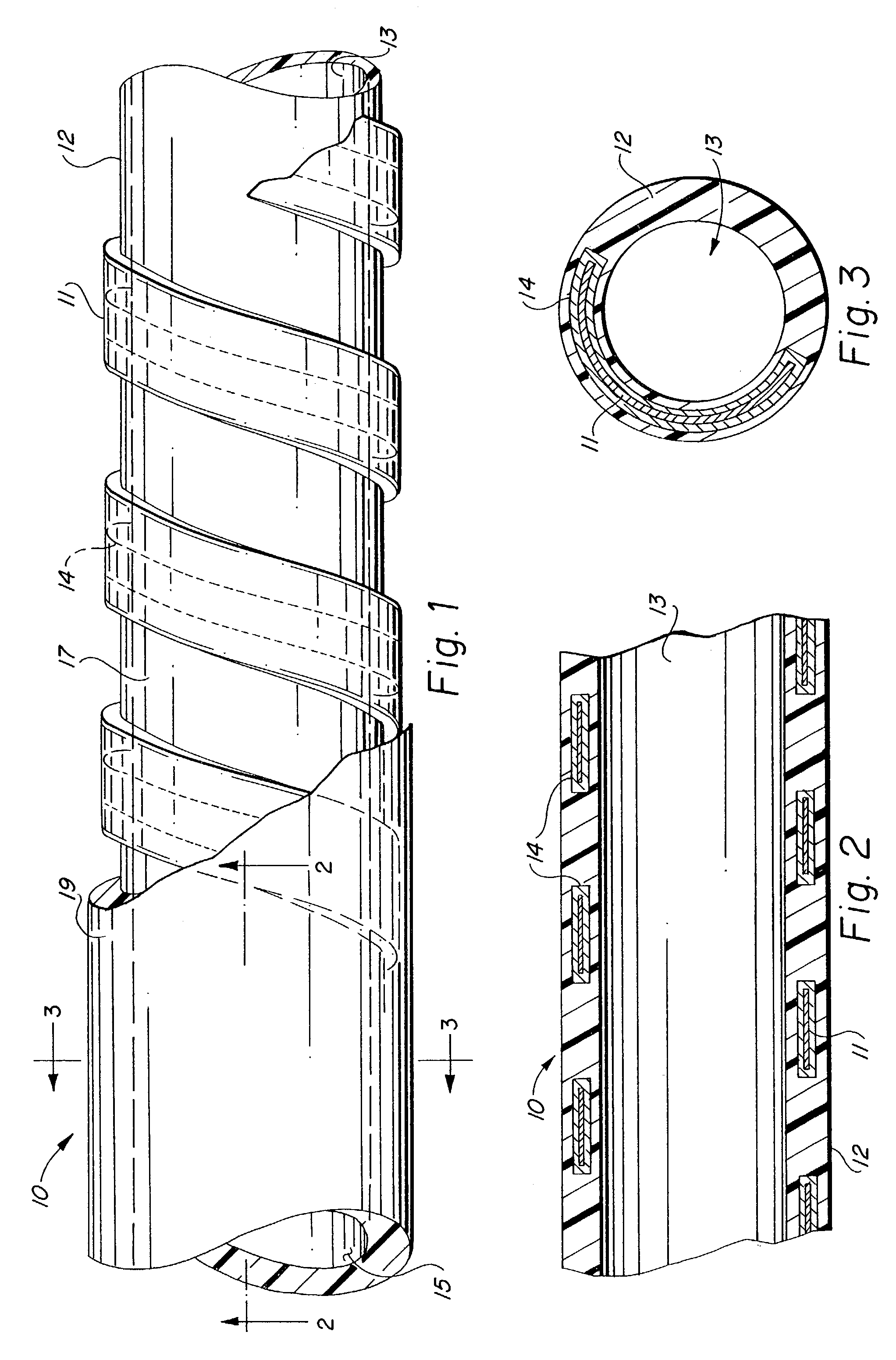
[0015]It is a primary objective of the present invention to provide a self-supporting, self-expanding stent-graft device which is capable of being delivered to an anatomical position within a human body in a first constrained configuration, positioned in vivo at a desired anatomical site, and the constraint released to permit the stent-graft device to transform to a radially enlarged second configuration.

Problems solved by technology

Conventional ePTFE vascular grafts, however, typically lack sufficient diametric mechanical rigidity to maintain luminal patency in intraluminal applications.
These externally supported ePTFE vascular grafts are not well-suited to interventional intraluminal procedures due to their inability to assume a reduced profile suitable for percutaneous delivery using a catheter and their inability to recover an enlarged diametric dimension in vivo.
A common problem of most conventional intraluminal stents is re-occlusion of the vessel after stent placement.
Tissue ingrowth and neointimal hyperplasia significantly reduces the open diameter of the treated lumen over time, requiring additional therapies.
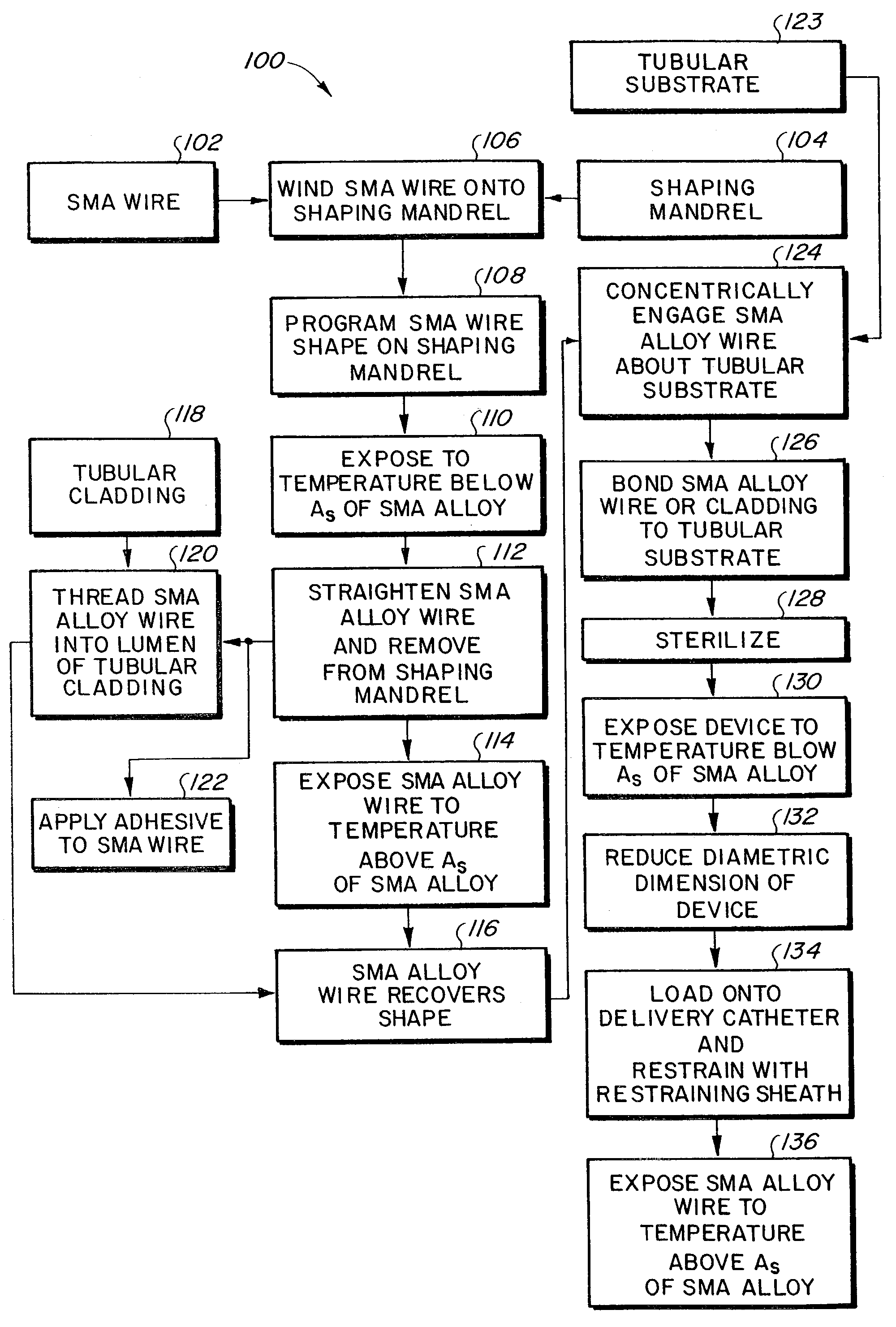
If the temperature is below As, the stress-induced martensite is stable, however, if the temperature is above As, the martensite is unstable and transforms back to austenite, with the sample returning to its original shape.

Method used


Image

  • Methods for making a supported graft
  • Methods for making a supported graft
  • Methods for making a supported graft

Examples


first embodiment

[0053]Turning now to FIGS. 5–12, there is depicted numerous alternate configurations of the polymer clad support wire member 14. FIGS. 5 and 6 depict the polymer clad support wire member 34 in which the support wire member is formed as a planar ribbon wire 38 a generally tubular box-like polymer cladding 36 provided about the outer surfaces of the planar ribbon wire 38. In the transverse cross-sectional view of FIG. 6 it will be seen that both the planar ribbon wire 38 and the polymer cladding 36 have generally quadrilateral cross-sectional configurations.

second embodiment

[0054]FIGS. 7–8 depict the polymer clad support wire member 40 in which the support wire member is formed as a cylindrical wire 44 having a generally tubular polymer cladding 42 provided about the outer circumference of the planar ribbon wire 44. In the transverse cross-sectional view of FIG. 8 it will be seen that both the cylindrical wire 44 and the polymer cladding 42 have generally circular cross-sectional configurations.

[0055]FIGS. 9–12 are provided in the transverse cross-sectional views only, it being understood that like FIGS. 5 and 7, each of the embodiments depicted in FIGS. 9–12 have corresponding perspective configurations. FIG. 9 depicts a third embodiment of the polymer clad support wire member 46 in which the support wire member is formed as a cylindrical wire having a generally triangular-shaped polymer cladding 48, with a central longitudinal cylindrical bore to accommodate the cylindrical wire 49 therein, which is provided about the outer surfaces of the cylindrica...


PUM

PropertyMeasurementUnit
inner diameteraaaaaaaaaa
wall thicknessaaaaaaaaaa

Abstract

A method for making an endoluminal prosthesis for implantation within a body lumen to maintain luminal patency, the prothesis including a support structure, such as a wire member, and a polymer component, such as a polymer cladding. The method may include joining a wire member to a polymer cladding, helically wrapping a length of the joined support wire member and polymer cladding such that adjacent windings of the polymer cladding have overlapping regions, and heating the joined support wire member and polymer cladding above the melt point of the polymer cladding.

Description

CROSS-REFERENCE TO RELATED APPLICATIONS[0001]This application is a divisional of U.S. patent application Ser. No. 09 / 855,918, filed May 15, 2001, now abandoned, which is a divisional of U.S. patent application Ser. No. 08 / 999,583, filed Dec. 22, 1997, now U.S. Pat. No. 6,264,684, which is a continuation-in-part of three applications: 1) International Application No. PCT / US95 / 16497, filed Dec. 8, 1995, which was nationalized as U.S. patent application Ser. No. 09 / 077,533, filed May 28, 1998, now U.S. Pat. No. 6,053,943; 2) U.S. patent application Ser. No. 08 / 833,797, filed Apr. 9, 1997, now U.S. Pat. No. 6,451,047, which is a continuation-in-part of U.S. patent application Ser. No. 08 / 508,033, filed Jul. 27, 1995, now U.S. Pat. No. 5,749,880, which is a continuation-in-part of U.S. patent application Ser. No. 08 / 401,871, filed Mar. 10, 1995, now U.S. Pat No. 6,124,523; and 3) U.S. patent application Ser. No. 08 / 794,871, filed Feb. 5, 1997, now U.S. Pat. No. 6,039,755. This applicatio...

Claims


Application Information

Patent Timeline
Patent Type & Authority Patents(United States)
IPC IPC(8): B32B37/00A61L31/00A61F2/00A61F2/06A61F2/88A61L27/50A61L31/04
CPCA61F2/86A61F2/07A61F2/88A61L31/048A61F2/06A61F2/82C08L27/18A61F2/0077A61F2002/072A61F2002/30093A61F2002/30448A61F2210/0019A61F2220/005A61F2210/0076A61F2002/075A61F2002/30092
Inventor BANAS, CHRISEDWIN, TARUN J.MCCREA, BRENDANKOWLIGI, RAJAGOPAL R.
Owner BARD PERIPHERAL VASCULAR
Why Eureka
Try Eureka