
Movable stringed instrument pickup system

a pickup system and stringed technology, applied in the field of stringed musical instruments, to achieve the effect of counteracting the diminution in volume, increasing the vibrational energy of strings, and reducing vibrational energy

Inactive Publication Date: 2006-06-13
SPALT MICHAEL SEBASTIAN
View PDF5 Cites 12 Cited by
  • Summary
  • Abstract
  • Description
  • Claims
  • Application Information

AI Technical Summary

Benefits of technology

"The present invention provides a pivoting electromagnetic pickup device for stringed instruments that can detect consistent tonal changes in all strings for a given pickup movement. The device has an elongated support structure that is pivotally attached to the instrument, with an electromagnetic pickup mounted in a fixed position between the support structure and the strings. The pickup detects the tonal changes of the strings through its movement relative to the strings. The device has an angular position locking means that can adjust the resistance to angular motion, and an adjustable nut to control the ease of movement of the pickup assembly. The device also has a recess to accommodate the curvilinear path of the pickup assembly without interfering with the strings. The elongated support structure can be made from various materials and the device can be electronically connected to the instrument's electronics cavity. The pickup assembly can also rotate about a pivot to counteract the diminution in volume caused by the reduced vibrational energy exerted by the strings in proximity to the bridge, and the rate of divergence between the pickup assembly and strings can be adjusted to maintain constant volume output throughout the range of motion of the pickup assembly."

Problems solved by technology

This limiting means can be any number of devices that can restrict the motion of the pickup assembly to a predefined sector.

Method used


Image

  • Movable stringed instrument pickup system
  • Movable stringed instrument pickup system
  • Movable stringed instrument pickup system

Examples


Embodiment Construction

[0023]The detailed description set forth below in connection with the appended drawings is intended as a description of presently-preferred embodiments of the invention and is not intended to represent the only forms in which the present invention may be constructed and / or utilized. The description sets forth the functions and the sequence of steps for constructing and operating the invention in connection with the illustrated embodiments. However, it is to be understood that the same or equivalent functions and sequences may be accomplished by different embodiments that are also intended to be encompassed within the spirit and scope of the invention.

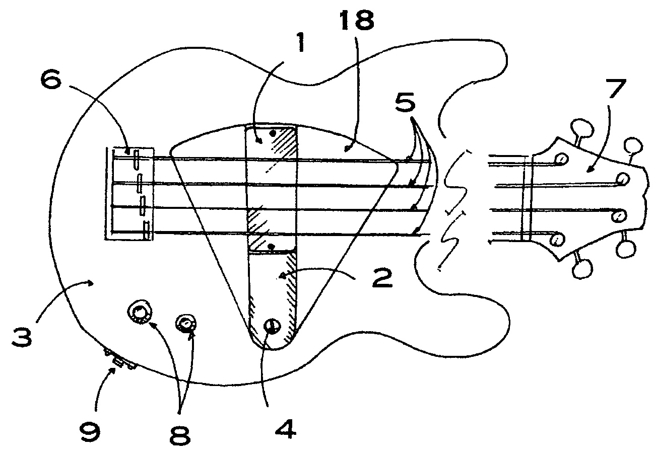
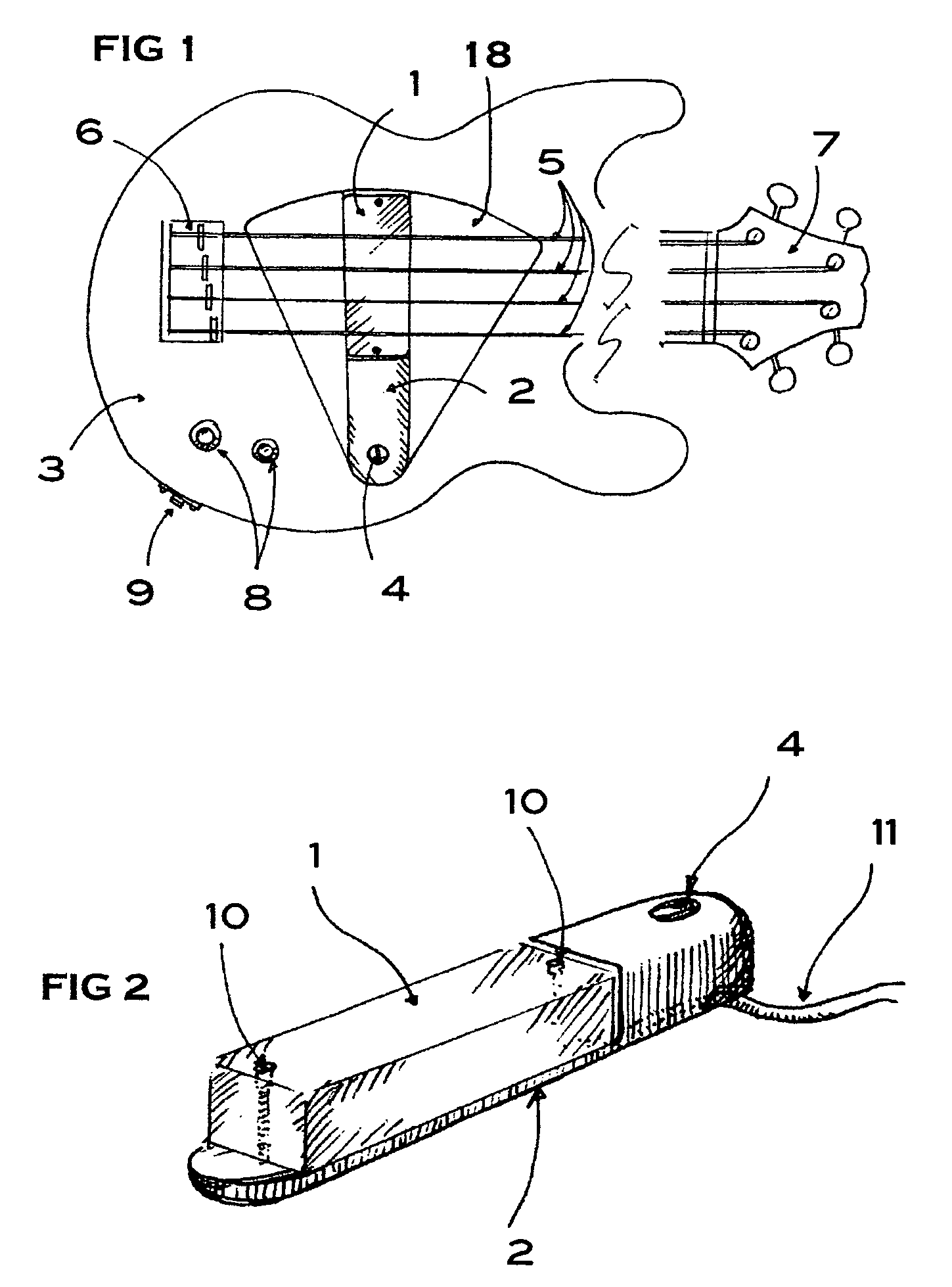
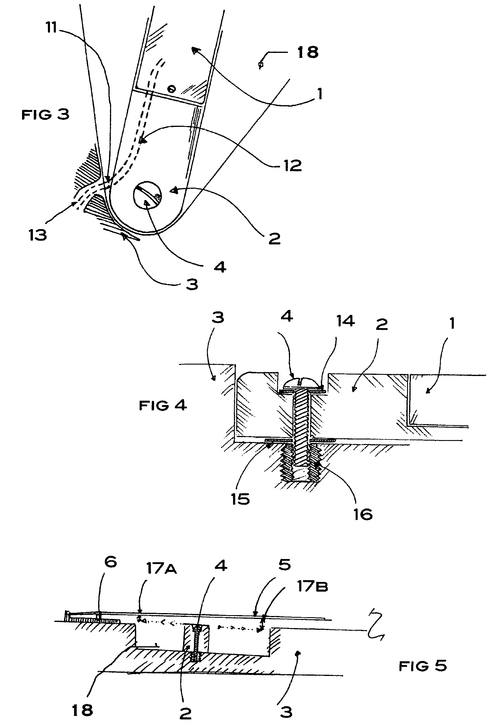
[0024]A top view of an electric stringed musical instrument, in this preferred embodiment a 4-string bass guitar, is shown in FIG. 1, having a neck and headstock with tuning mechanisms (7), strings (5) which are anchored to the body (3) by the bridge (6). The pickup (1) is shown mounted on the elongated support structure (2), in this pr...


PUM


Abstract

A pivoting electromagnetic pickup device is provided. The invention generally is comprised of an elongated support structure, an electromagnetic pickup, a pivoting means, and an angular position locking means. The extremity of the elongated support structure is pivotally attached to the front face of an electric guitar or electric base body, between the front face and the strings, restricting its movement to a curvilinear path substantially normal to the axis of rotation and substantially parallel to the plane of the strings. The pickup is mounted to the elongated support structure, between the elongated support structure and the strings. Attaching the elongated support structure to the guitar body in a pivotal relationship is the pivoting means. The angular position locking means can be engaged to continuously vary the resistance to angular motion, from no resistance to maximum resistance, where the elongated support structure is substantially locked to a chosen angular position.

Description

BACKGROUND OF INVENTION[0001]This invention relates to stringed musical instruments in general and, more particularly, to electric guitars and basses having a movable electromagnetic pickup.[0002]The initial design of electric stringed instruments, such as electric guitars and basses, included an electromagnetic pickup device, to detect the mechanical waves of the strings within the magnetic field; and, in turn, the magnetic disturbance is converted to an electric signal, transmitted to a sound amplifying means. The single pickup was positioned under the strings, at a fixed position. In order to improve the musical performance and flexibility of stringed instruments, multiple pickup and movable pickup devices were soon introduced.[0003]The purpose of positioning the pickup along different sections of the vibrating strings is to affect a change in the sound quality of the instrument. The closer a pickup is to the bridge of a stringed instrument, the more it will pick up treble freque...

Claims


Application Information

Patent Timeline
Patent Type & Authority Patents(United States)
IPC IPC(8): G10H3/14G10H3/18
CPCG10H3/183
Inventor SPALT, MICHAEL SEBASTIAN
Owner SPALT MICHAEL SEBASTIAN
Learn More