Communication device which requests transmission of encoded data based on monitored reception quality

a technology of transmission device and encoded data, which is applied in the field of communication device which requests transmission of encoded data based on monitored reception quality, can solve the problems of serious degradation of the quality of the reproduced image, inability to transmit data, and inability of mobile stations to reproduce received data properly, so as to achieve the effect of restoring the quality of the received and reproducing data in a short tim

Inactive Publication Date: 2006-06-13
KK TOSHIBA
View PDF6 Cites 6 Cited by
  • Summary
  • Abstract
  • Description
  • Claims
  • Application Information

AI Technical Summary

Benefits of technology

[0008]The object of the present invention is to provide a data transmission system capable of restoring the quality of the received and reproduced data in a short time, even if the quality of the received and reproduced data has deteriorated seriously due to the degradation of transmission quality, and communication devices used in the system.
[0015]Therefore, with the present invention, even if the transmission quality of the channel has deteriorated for a long time and consequently the quality of the data reproduced on the reception side has deteriorated seriously, the transmission side transmits the first data to the reception side in place of the second data after the restoration of the transmission quality has been detected. As a result, the reception side restarts reproducing the data on the basis of the first data transmitted from the transmission side, after the transmission quality has been restored. This makes it possible to restore the quality of the received playback data to the good quality before the restoration in a short time.
[0016]Particularly in a radio data transmission system using a radio communication circuit, the reception field strength at a mobile station varies sharply as the mobile station moves. As a result, the data reception quality deteriorates frequently. The transmission side, however, transmits the first data to the reception side automatically each time the data transmission quality has been restored after the deterioration of the data transmission quality as described above. This makes it possible to always restore the quality of the reception playback data quickly after the restoration of the transmission 5 quality, which is quite effective in radio communication.

Problems solved by technology

In the present mobile communication system, however, if a large amount of data, such as moving picture data, were transmitted, transmission channel band would become a bottleneck, making it impossible to transmit the data as it is.
When the reception field strength has dropped below the level represented by a broken line H necessary to secure a specific error rate, the mobile station cannot reproduce the received data properly.
As a result, the quality of the reproduced image deteriorates seriously.
Therefore, a lot of time elapses until a good image can be reproduced.

Method used


Image

  • Communication device which requests transmission of encoded data based on monitored reception quality
  • Communication device which requests transmission of encoded data based on monitored reception quality
  • Communication device which requests transmission of encoded data based on monitored reception quality

Examples


second embodiment

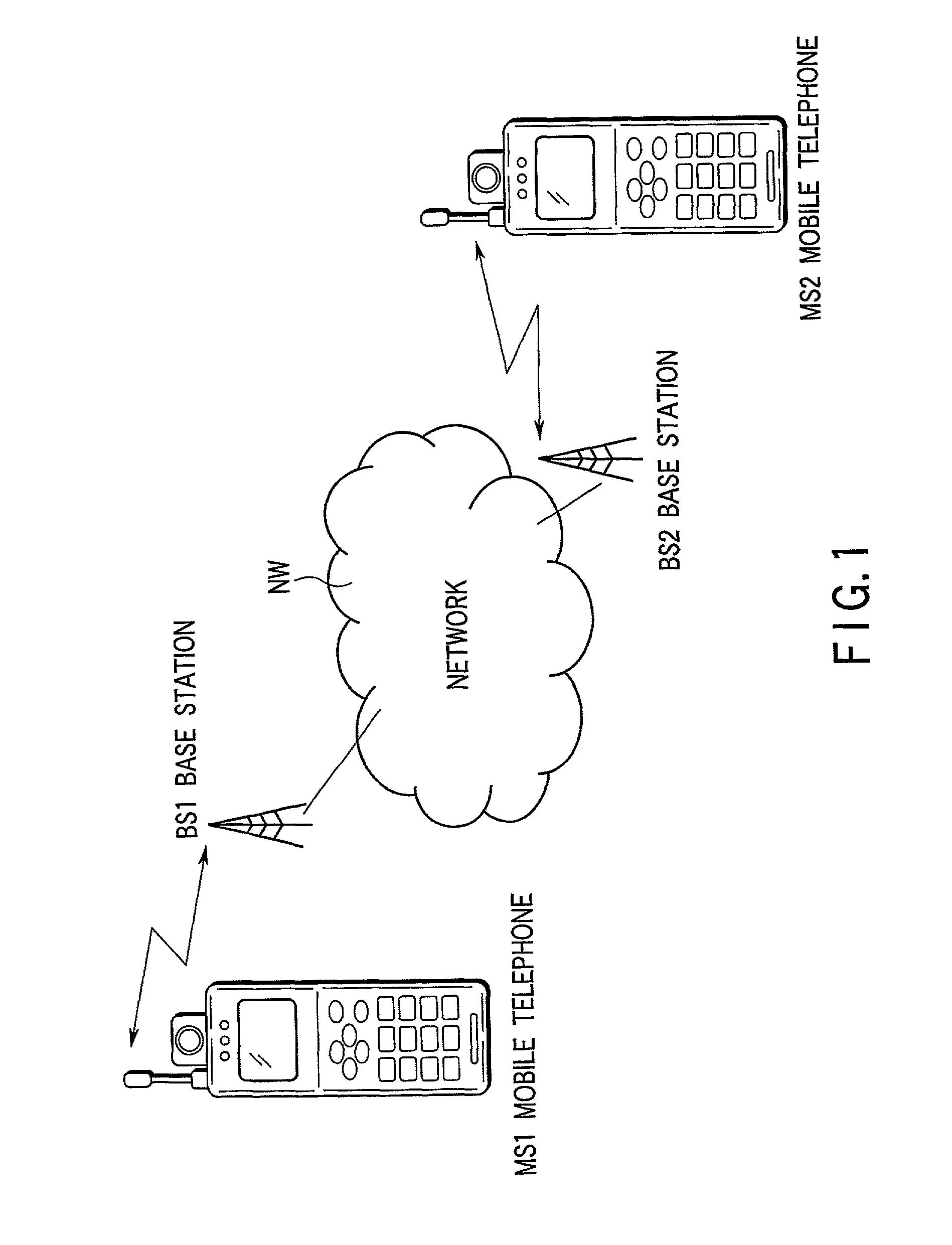
[0067]In a second embodiment of the present invention, when wireless video telephone communication is performed between mobile telephones using an MPEG-4 image compression scheme in a mobile communication system, the detect data about the reception field strength detected by a mobile telephone which receive a MPEG-4 image data during data reception is notified to a mobile telephone which transmits a MPEG-4 image data.

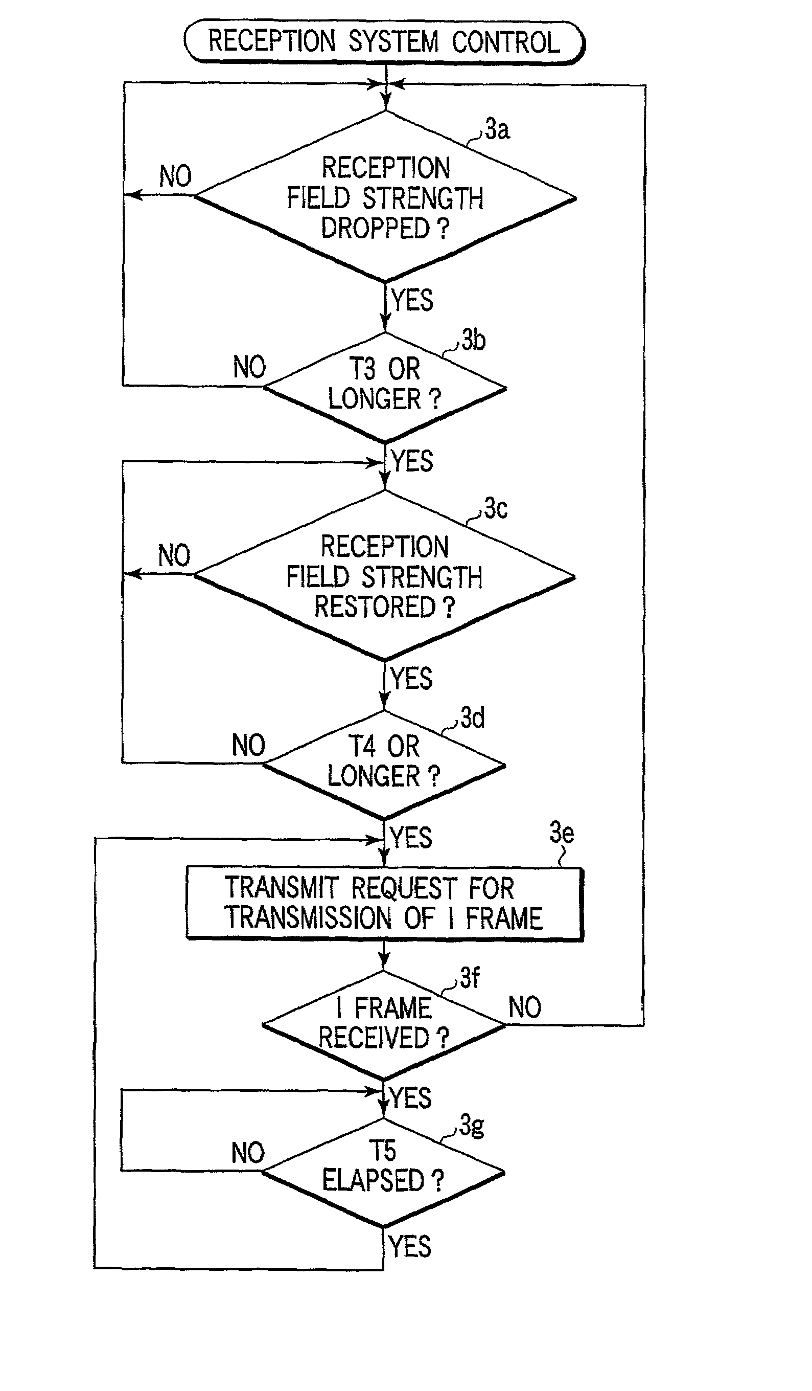
[0068]Then, the mobile telephone on the transmission side monitors a drop in and the restoration of the reception field strength at the receiving mobile telephone on the basis of the notified reception field strength detect data. When detecting the restoration, the transmitting mobile telephone transmits an I frame to the mobile telephone on the reception side in place of a P frame.

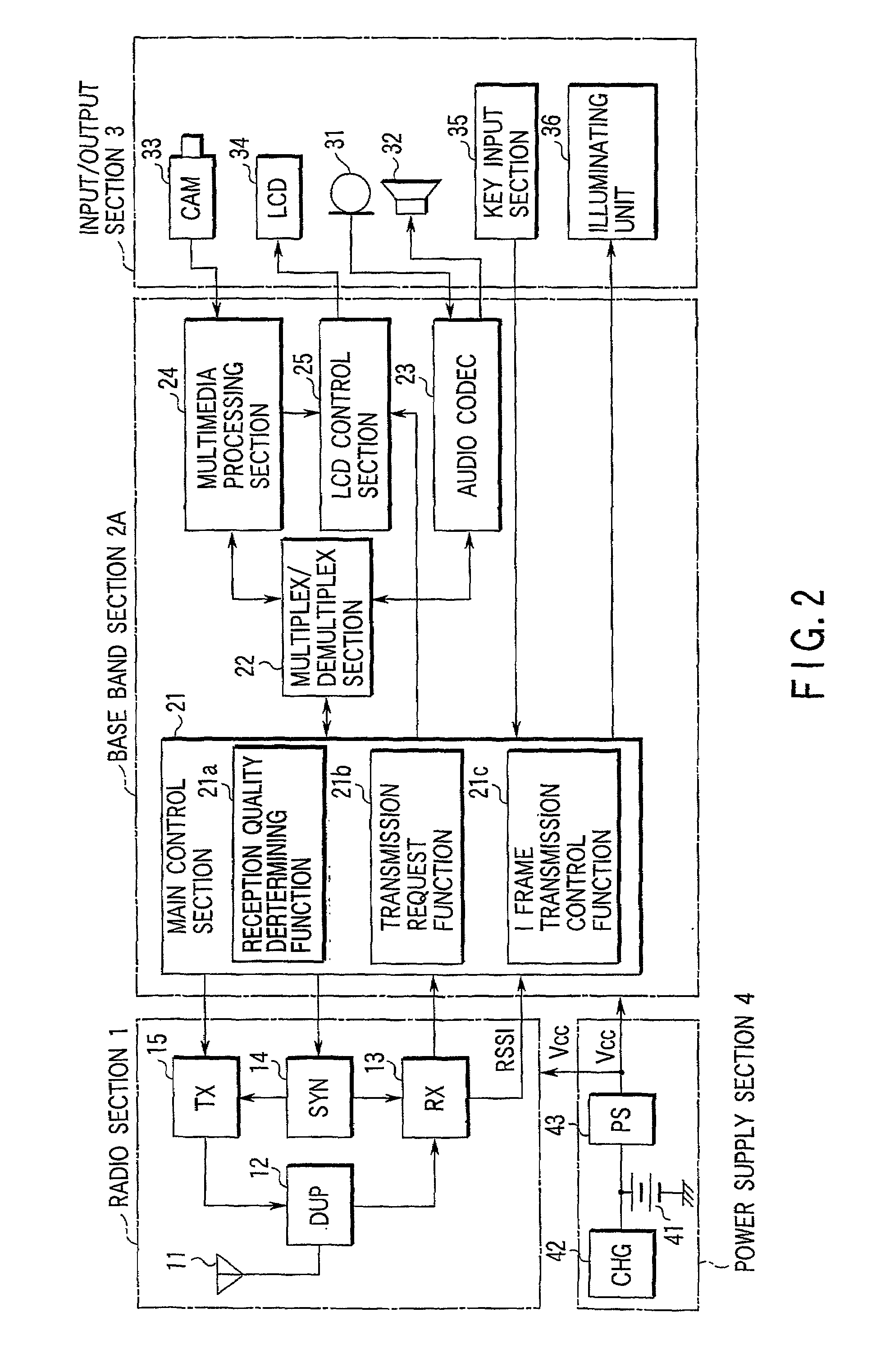
[0069]FIG. 6 is a block diagram showing the functional configuration of a mobile telephone according to the second embodiment. In FIG. 6, the same parts as those in FIG. 2 are indicated by th...

third embodiment

[0079]In a third embodiment of the present invention, each mobile telephone has a record control function for received data in addition to the control functions explained in the first embodiment. When the record control function has detected the deterioration of the reception field strength at its own telephone, it retrieves the video data received and recorded from the time when the deterioration was detected until the I frame has arrived from the mobile telephone after the restoration of the reception field strength, and deletes the retrieved video data from the recording memory.

[0080]FIG. 8 is a block diagram showing the functional configuration of a mobile telephone according to the third embodiment. In FIG. 8, the same parts as those in FIG. 2 are indicated by the same reference numerals and a detailed explanation of them will not be given.

[0081]The baseband section 2C includes a memory section 26. The memory section 26 is composed of, for example, a flash EEPROM and used to re...


PUM


Abstract

In this invention, wireless video telephone communication between mobile telephones MS1 and MS2 using the MPEG-2 standard is performed when the reception field strength falls below a threshold value of H continuously for a specific period of T3 or longer in the course of receiving the data at one mobile telephone MS2, the telephone MS2 monitors the restoration of the reception field strength. After detecting the restoration, mobile telephone MS2 transmits a request for the transmission of an I frame to mobile telephone MS1. Upon receipt of the request, mobile telephone MS1 creates an I frame in place of a P frame and transmits the I frame.

Description

TECHNICAL FILED[0001]This invention relates to a data transmission system employing a data compression / expansion scheme of transmitting absolute value information in the initial frame and information on the difference from the preceding frame in each subsequent frame and communication devices used in the system.BACKGROUND ART[0002]In recent years, portable communication terminals, such as mobile telephones or PDAS (Personal Digital Assistants), have begun to make various information transmission services available to people. The information transmission services include audio communication service, SMS (Short Message Service, electronic mail service, and information delivery service using a wireless Internet. In the present mobile communication system, however, if a large amount of data, such as moving picture data, were transmitted, transmission channel band would become a bottleneck, making it impossible to transmit the data as it is.[0003]Thus, to transmit moving picture data by ...

Claims


Application Information

Patent Timeline
Patent Type & Authority Patents(United States)
IPC IPC(8): G01R31/08H04B7/26H04N19/114H04N1/00H04N7/14H04N7/24H04N19/166H04N19/44H04N19/50H04N19/65H04N21/414H04N21/442H04N21/4788H04N21/6377H04N21/6379H04N21/658H04W16/02H04W28/00H04W28/06H04W28/18H04W72/04H04W88/02
CPCH04N1/00106H04N21/41407H04N21/44209H04N21/6377H04N21/6379H04N21/658H04N21/4788H04W28/06
Inventor ITO, KOICHIYAMAGUCHI, KENTOKUINOUE, NOBUHIROSATO, YUICHISAKUMA, KEIOURA, SEIJIOKA, TOMEOKATAOKA, YOSHIHIROOGASAWARA, HIROSHI
Owner KK TOSHIBA
Why Eureka
Try Eureka